Tutorial: Switch, transistor and Buzzer on Breadboard
Let start with building something interesting, in the previous tutorial you seen the functionality of LED and we taught you the basics of breadboard, in this section we are going to show something more interesting, this tutorial is mainly focused on transistors which is basic common part in all of today’s electronics, they are just simple switches that we can use to turn things on and off. Even though they are simple, they are the most important electrical component. These are basic building block of any Integrated Circuits(IC), For example, transistors are almost the only components used to build a Pentium processor. A single Pentium chip has about 3.5 million transistors. The ones in the Pentium are smaller than the ones we will use but they work the same way.
To understand transistor better we will start with one of the basic component we seen in electronic circuit, its nothing but switch, refer the image below:
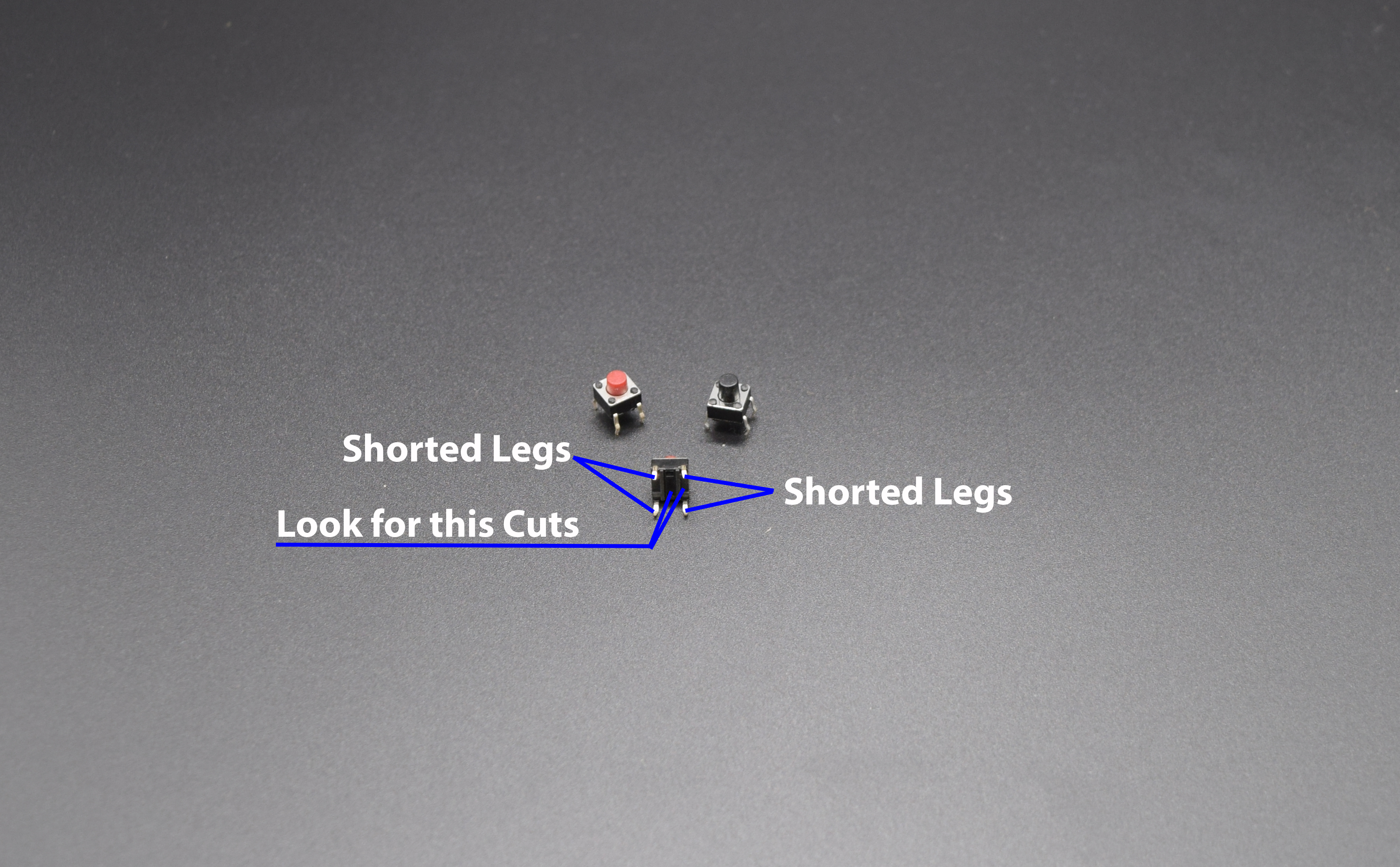
These switches are nothing but momentary push buttons, means when you press them then only it will be functional(i.e ON) otherwise it will remain OFF. Lets build a simple circuit on breadboard using a switch, refer the image below to build your circuit:
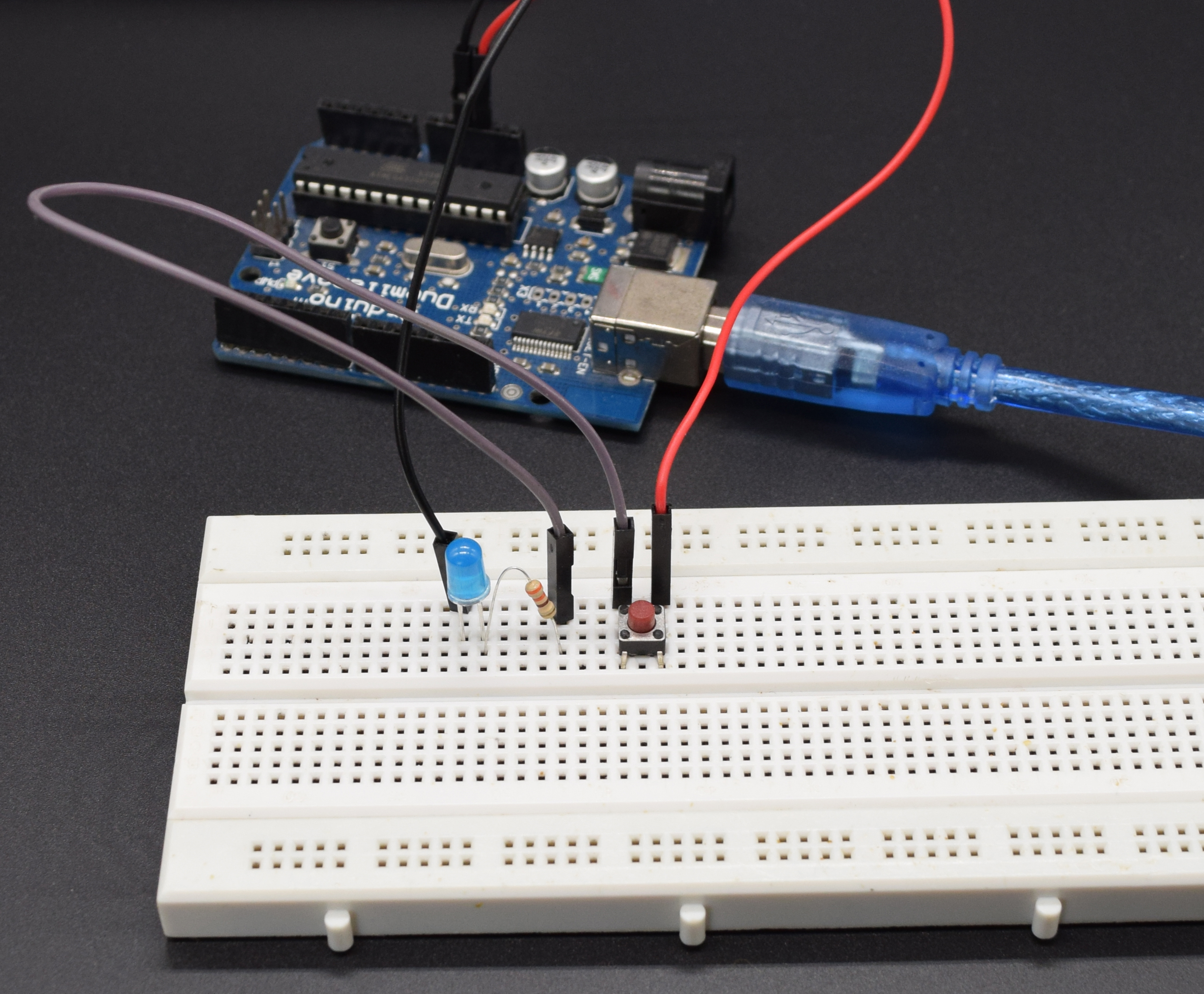
Note: We had Connected 5v supply and GND from Arduino board in the above image, you can use Raspberry Pi or any other boards you having with you to supply 5v and GND from the board. If you having our Raspberry Pi Electronics Starter kit with you, then you can use the RasPiO Portplus we provided with the kit, to find the 5v and GND pins on Raspberry Pi and use the Male-Female Jumper wire we provided in the Kit to Supply power to the LED-Switch Circuit on breadboard.
Now if you see, you can understand that this circuit is nothing but modification of the previous LED breadboard tutorial, here we have added one switch to the LED circuit. Care must be taken when you connect the switch. Out of four legs you will get two shorted legs, as described in the image, you refer the cut mark on the bottom of the switch to understand which sides of the switch are shorted. Make sure that the mark on the switch and the breadboard columns should match otherwise your switch will not functional properly.
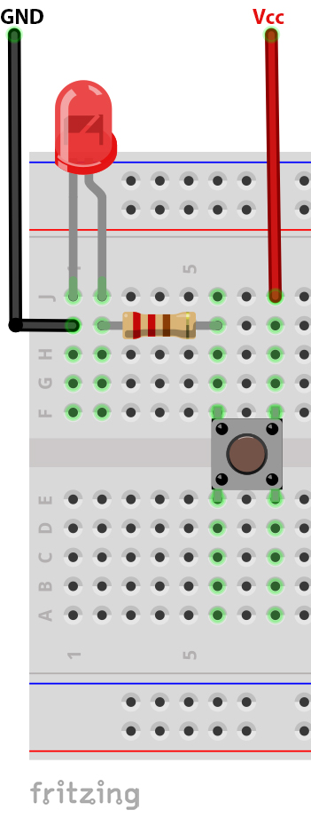
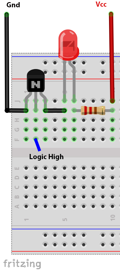
When you power the above circuit, the LED won’t glow, its because the circuit is controlled by Switch now, so if you press the Switch now, you will see that the LED will remain On till the moment you press the Switch, otherwise it will remain off. The transistors works in similar fashion, its works as Switch, except that, with switch you need to use your hands to push it and made the LED glow, here with transistors you need to apply logics to turn the LED ON and OFF. Thus applying logic’s will simulate the key press in the transistor.
All the Electronic Components runs on two logic’s only 1(HIGH) and 0(LOW), When you apply Logic High to transistor the transistor will either turn ON or turn OFF depending on the transistor type. Before we see the types, we will clear you what this Logic High and Low Means. Any Electronic Machine understands only two voltages/ Logic’s and they are Vcc/ Logic 1(High) and Gnd/ Logic 0(LOW)
Now, we will see what are types of transistor:
- NPN
- PNP
The NPN is nothing but N-Type transistor, which will activates when you supply a Logic High to it. Similarly, The PNP is nothing but P-Type transistor, which will activates when you supply a Logic Low to it.
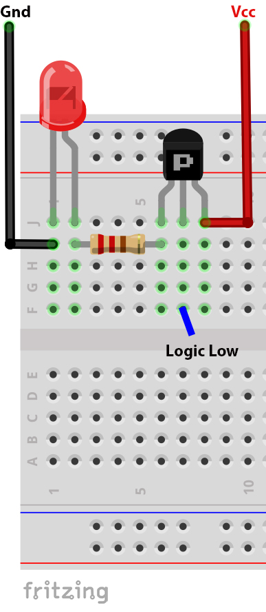
Refer the two different types of circuit shown above, you will clearly understand the difference between the two types of transistors working. The P type will turn on the LED when you applied Logic low to the transistor and the N type will turn on the LED, when you apply Logic High to the transistor.
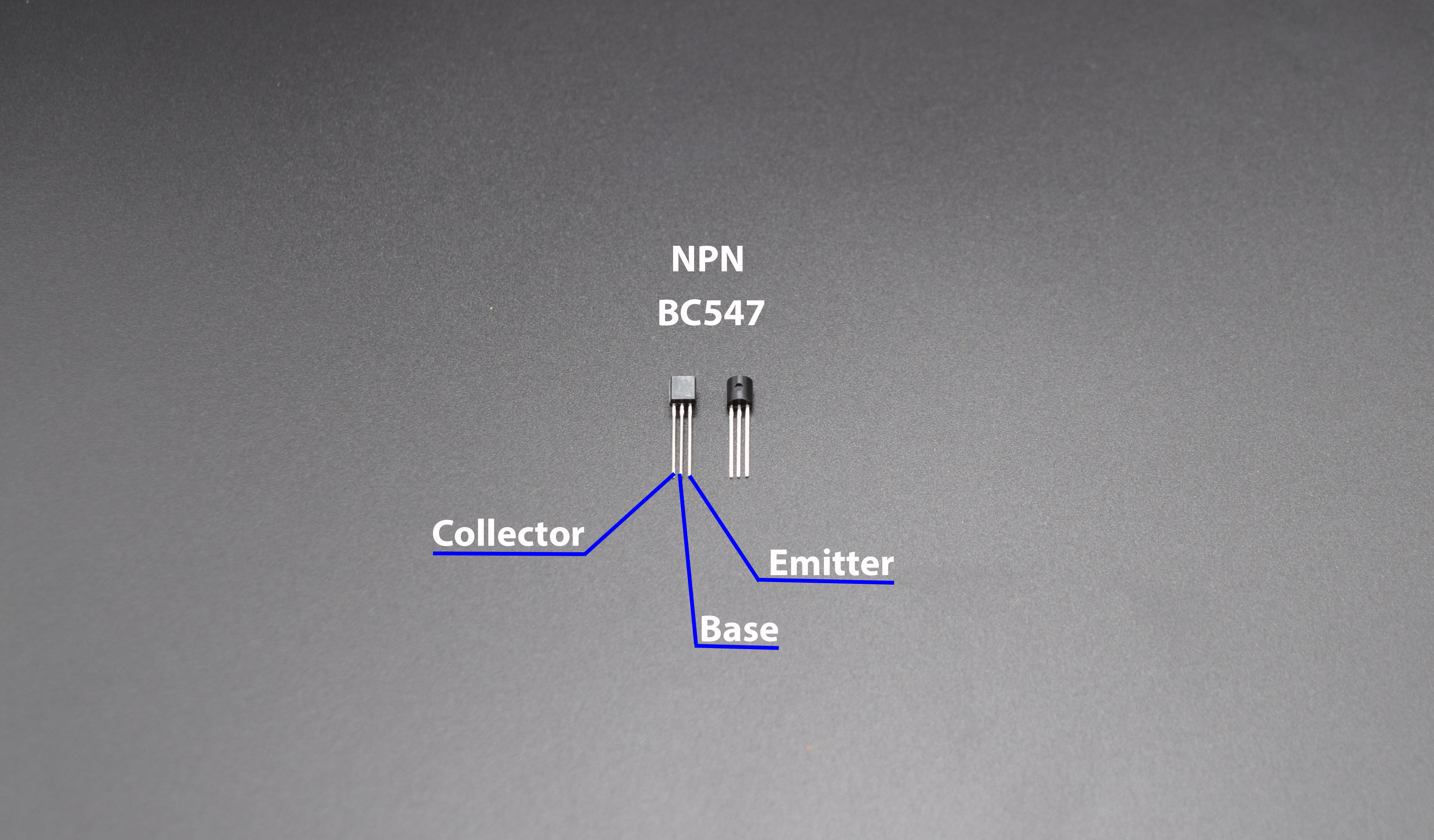
Note: The logic’s will be applied to base/gate Pin of transistors, the other two pins are emitter/drain and Collector/source.Collector/Source pin used to connect the transistor from power source and emitter/drain pin used to connect with loads.The Pin descriptions are mentioned in the datasheet of each transistor, so there is no need to worry about it as of now.
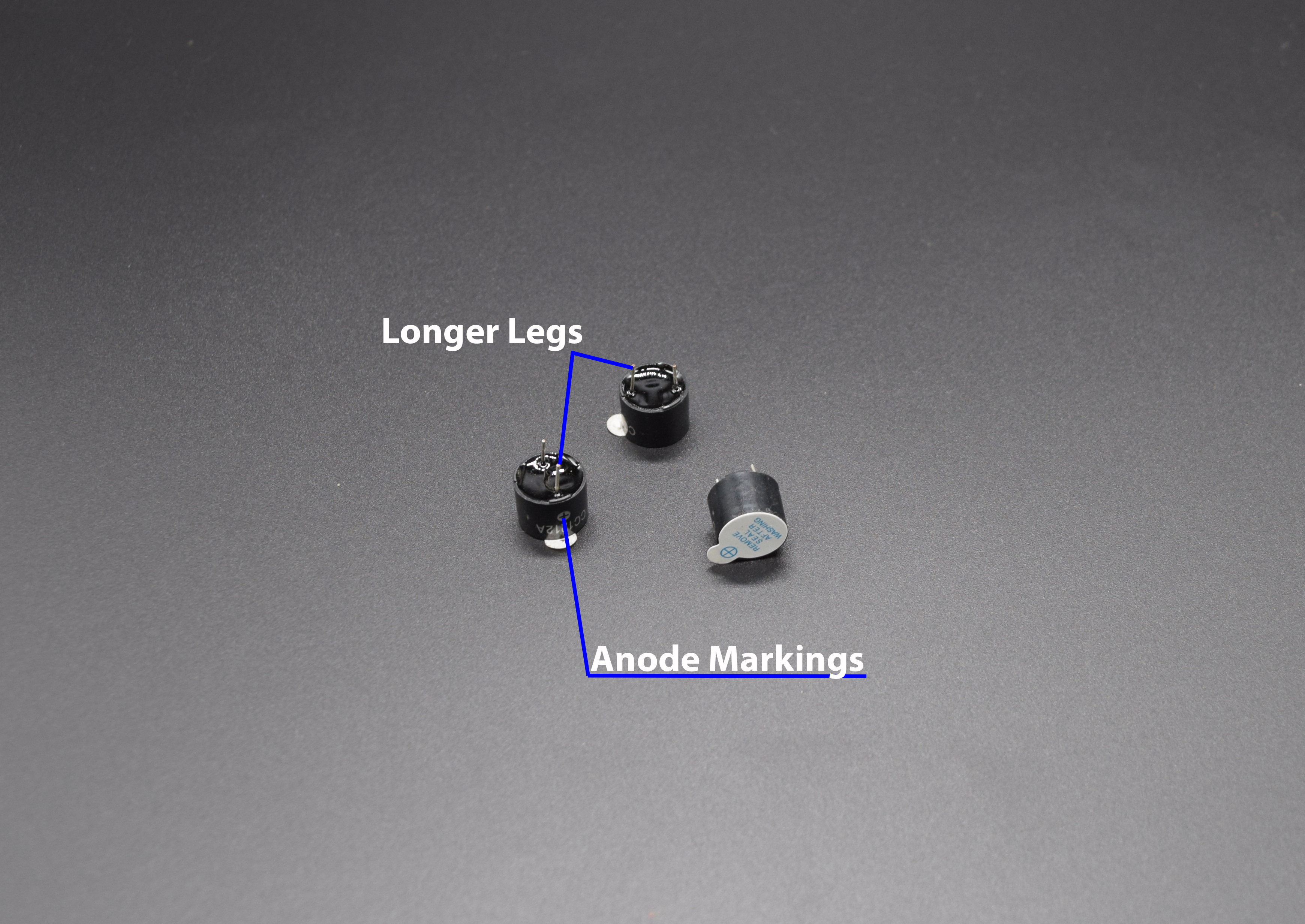
Now we will move one step further and add some sound to the project, till now when we press the switch or apply the logic’s to transistor the LED will lit up. let us add one piezo buzzer to the breadboard and see what happens when we press the switch.
Refer the schematic below to build your own circuit in a breadboard.
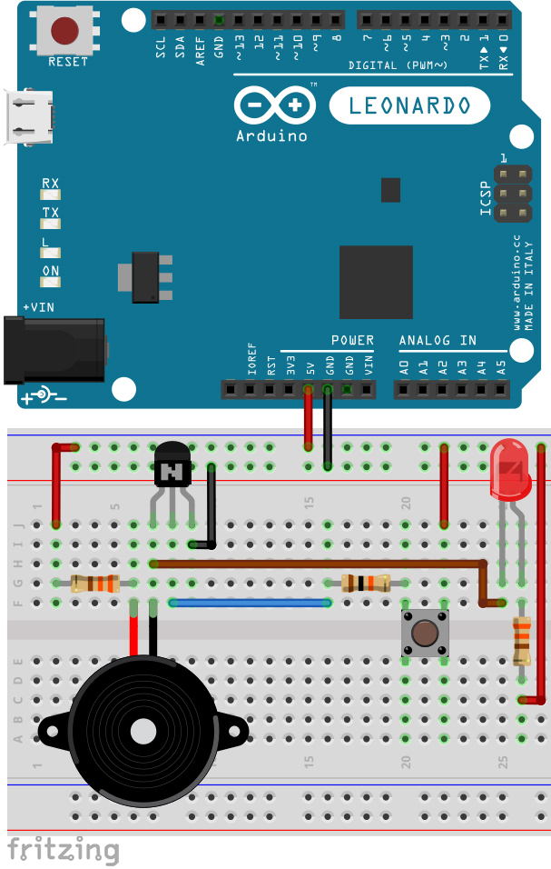
In the above shown example we had used Arduino as 5v power source to power the breadboard, you can use any other power source as per you convenience. Now if look at the circuit we had Used N-type(NPN) transistor, now if you google for BC547 Datasheet, you will see lots of options, open any one datasheet .pdf document, once you scan through all the pages you will notice lots of details about transistor is mentioned in it, right now we are focusing on the type, voltage and current of the transistor. If check you will see all these data withing the first 5 pages. There its mentioned:
BC547
- NPN Epitaxial Silicon Transistor
- Vceo: 45v
- 100mA
we seen that its N-Type(NPN) and its maximum voltage is 45v which is more than enough, since we are running only on 5v. Regarding current, if we calculate the current required for the loads, the LED needs 15mA and the buzzer needs 40mA max, thus combining two, its comes under 60mA, thus we are good to go with same transistor. If your loads exceeds the rated current go for higher current transistor. Refer the image below for the Pin description of the BC547 Transistor we are using.
You can see that we are supplying High Logic from switch to transistor, so when you press the switch the Vcc(5v) will be applied to gate pin of transistor and this will activate the transistor, allowing the current to flow through LED and Buzzer and in return we can see and hear the light and sound respectively.
Note: Don’t forget to add current limiting resistor for buzzer and resistor and polarity of the buzzer must be taken care of similar to that of LED.
So, this is all about the welcome little step you made into hands on with electronics, in the next tutorial, we will show you how to use microcontrollers/Arduino to control these kind of circuits.
0 Comments
Trackbacks/Pingbacks