Getting Started with Raspberry Pi and Electronics
New to Electronics or programming ? No need to worry now, the Raspberry pi is only for you. If you are beginner, we will recommend you to go through our Raspberry Pi Blogs. We will recommend you to go through these set of videos before getting started. Lets have a look at set of contents we are covering in this tutorial.
-
Hardware Needed
-
Using RasPiO Portsplus with Raspberry Pi
-
Getting Started With Breadboard and LED
-
Getting Started with Switch, transistor and buzzer on breadboard
-
Pi Wedge Hookup Guide
-
Getting Started with Physical Computing on Raspberry Pi
-
Getting Started with Scratch
-
Test blinking LED using Python/Scratch
-
Testing Switch using Python/Scratch
-
Testing Capacitive Touch using Python/Scratch
-
Testing Buzzer using Python/Scratch
-
References
Hardware Needed
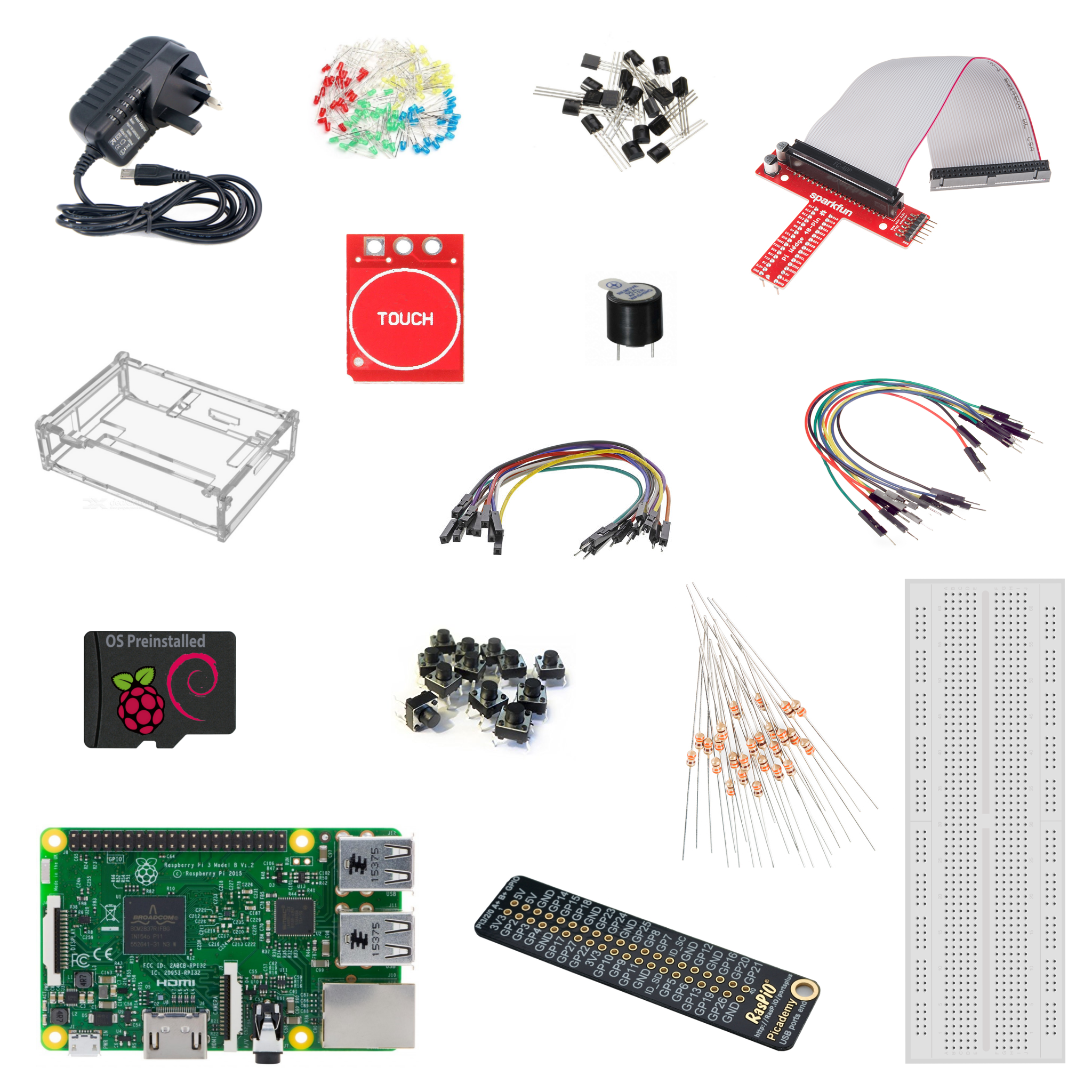
Raspberry Pi Electronics Starter Kit
RasPiO Portsplus
The RasPiO® Portsplus board is designed for the new Raspberry Pi 3/2/A+/B+. It labels the ports clearly for you so that you don’t need to count pins. This will help you avoid wiring errors and damage.You can slip it over the GPIO header if you want, or hold it next to the header.RasPiO® Portsplus has GPIO port numbers on one side and Pin numbers on the other side, so you can use whichever numbering system you prefer. At just 1mm thick, it leaves plenty of space for attaching your wires. It’s thick enough not to feel flimsy, but thin enough not to be clunky. Refer the image below, to see how to use RasPio Portsplus.
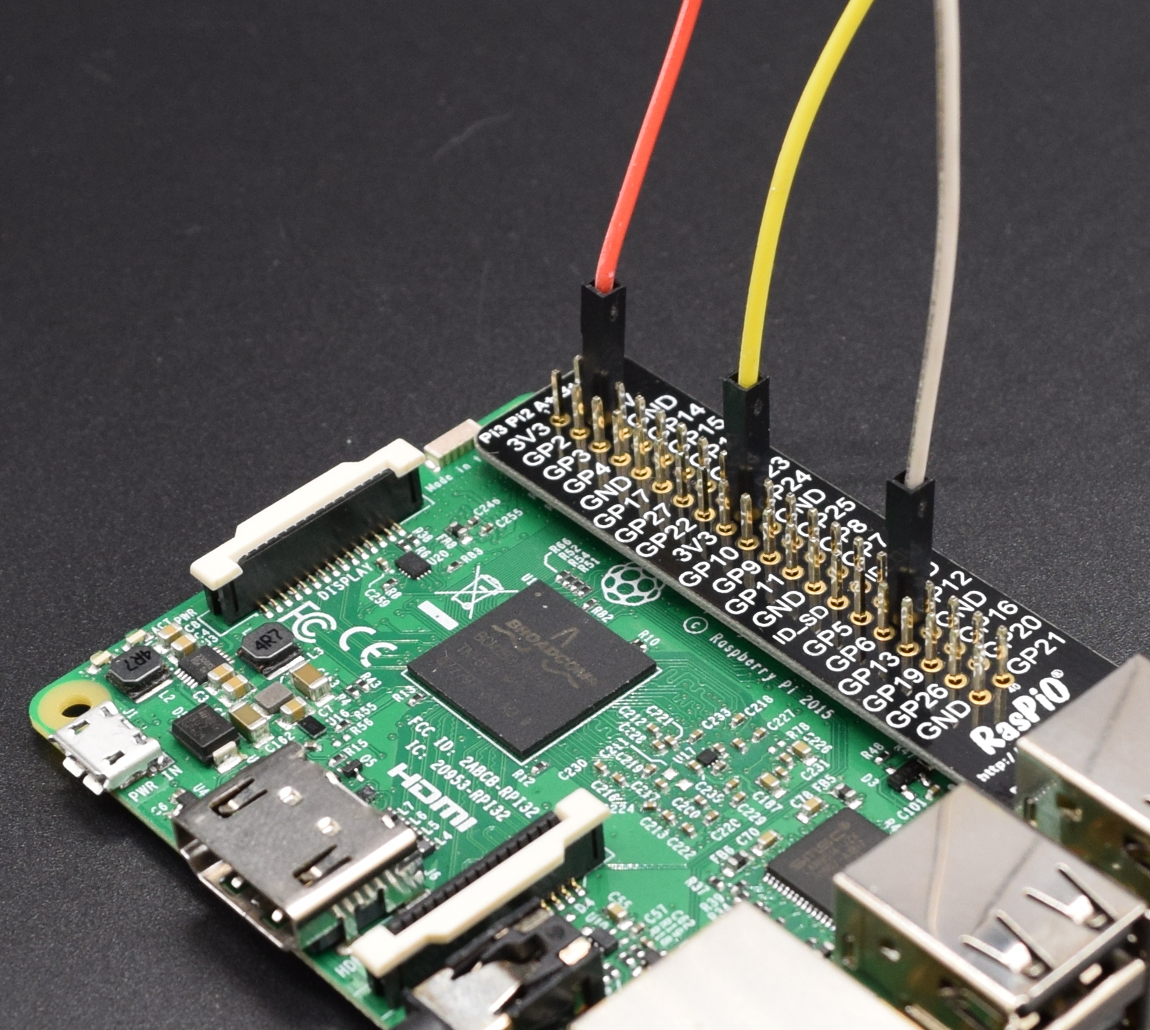
Raspberry Pi with RasPiO Portsplus and jumpers
Breadboard and LED
In this step we will start with the breadboard, breadboards are preferred platform to start building circuits because it don’t need any soldering, thus giving you the flexibility to try, test and modify your circuit at any point of time. They allow you to make quick circuits, test out ideas and allow prototyping before making a permanent Printed Circuit Board. They are inexpensive and reusable and they are easily available in any electronics store. Once you understood the basics regarding breadboading , then will go ahead with the basic essential component of all the electronics circuit i.e LED.We have already added all the details regarding this step in the following blog, refer this blog on ” How to Breadboard LED “
Getting Started with Switch, transistor and buzzer on breadboard
One of the most elementary and easy-to-overlook circuit component is the switch. Switches don’t require any fancy equations to evaluate. All they do is select between an open circuit and a short circuit. Simple. But how could we live without buttons and switches!? What good is a blinky circuit with no user input? Or a deadly robot with no kill switch? or any remote or mobile with no buttons? What would our world be without with big red buttons.A switch is a component which controls the open-ness or closed-ness of an electric circuit. They allow control over current flow in a circuit (without having to actually get in there and manually cut or splice the wires). Switches are critical components in any circuit which requires user interaction or control.A switch can only exist in one of two states: open or closed. In the off state, a switch looks like an open gap in the circuit. This, in effect, looks like an open circuit, preventing current from flowing.In the on state, a switch acts just like a piece of perfectly-conducting wire. A short. This closes the circuit, turning the system “on” and allowing current to flow unimpeded through the rest of the system.
A circuit with an LED, resistor, and a switch. When the switch is closed, current flows and the LED can illuminate. Otherwise no current flows, and the LED receives no power.
There are tons and tons of switches out there: toggle, rotary, DIP, push-button, rocker, membrane, … the list just goes on and on. Each of those switch types has a set of unique characteristics to differentiate it from others. Characteristics like what action flips the switch, or how many circuits the switch can control. You can check the different types of switches we having with us.Transistors can be regarded as a type of switch, as can many electronic components. They are used in a variety of circuits and you will find that it is rare that a circuit built/available in school Technology Department/ Laboratory does not contain at least one transistor. Even the things you used in your daily life, i.e mobile, tv, computers, etc all comes with tons of transistors built into it, transistors are central to electronics and there are two main types; NPN and PNP. Most circuits tend to use NPN. There are hundreds of transistors which work at different voltages but all of them fall into these two categories.We had added detailed tutorial on ” Getting started with switch, transistors and buzzer on breadboard “ , so that you will clearly understand the basics of switches, transistors and buzzer.
Pi Wedge
Its time to expand your GPIO pins from the Raspberry pi and made it accessible for Breadboarding. The preassembled 40-pin Pi Wedge will let your Pi pins broken out to a breadboard so that they can easily be used. The Sparkfun has already added a detailed hookup guide on their website, we will recommend you to refer this tutorial to understand pi-Wedge better.
Physical Computing on Raspberry Pi
The Raspberry Pi learning resource is provided for free by the Raspberry Pi Foundation under a Creative Commons licence, which we are able to access from their website, you can find the resources here, We have provided all the items in the Electronics Starter Kit to get started with mentioned tutorial, all you need to do is follow the steps mentioned in the getting started tutorial to understand the basic principles of interfacing individual items. please go through this guide on “Getting Started with Physical Computing on Raspberry Pi “
Scratch
Scratch is a visual programming tool which allows the user to create animations and games with a drag-and-drop interface. It allows you to create your own computer games, interactive stories, and animations using some programming techniques without actually having to write code. This resource will help get you started with the basics of Scratch. The Raspberry Pi learning resource is provided for free by the Raspberry Pi Foundation under a Creative Commons licence, which we are able to access from their website, you can find the resources here, please go through “Getting Started with Scratch on Raspberry Pi Tutorial” to understand the various features and application of the Scratch tool.
Blinking LED
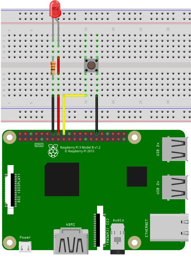
Since you have already seen some basic programming in the getting started section, we are adding one more advancement in the LED circuit and code here, we will recommend you to build the following circuit in your breadboard:
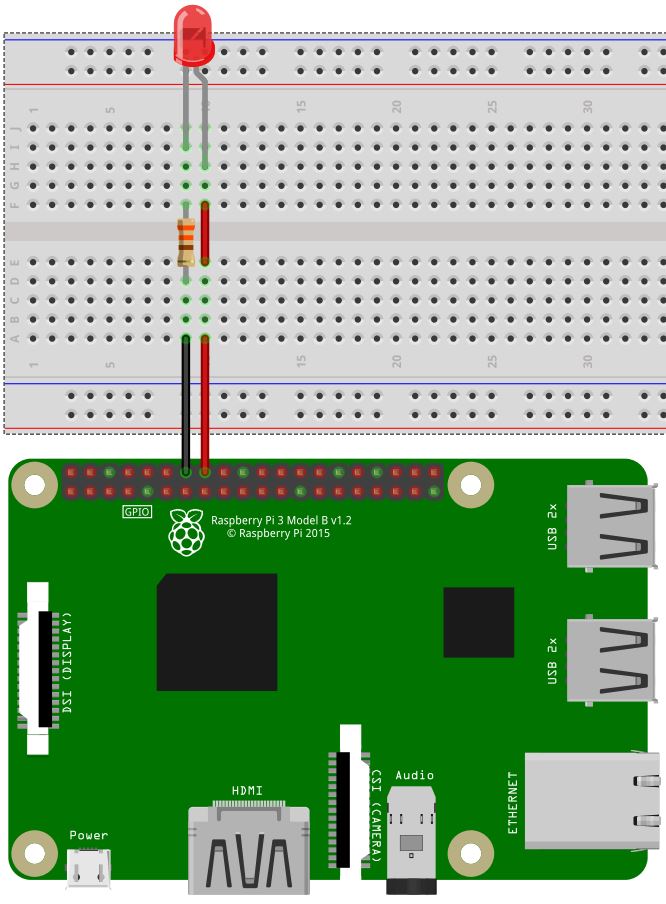
Blinking LED Circuit
To begin with, we will recommend you to open the IDLE from the following path: Menu -> Programming -> IDLE 3/Python 3 and you will find the Scratch in the Same path as well: Menu -> Programming -> Scratch.We had added the python code and Scratch Project in the following link, you can save/download the file in your system, click on the respective icon to open/download the file.
|
|

You can refer to scratch program in the image below:

LED Blinking
Switch
In this step you have to add switch connection to the LED connections you made in the previous step. Follow the circuit shown below:
Switch Connection
Now refer the Scratch and Python Code to get it working
|
|
You can refer the Scratch program in the blow image:

Contro LED Using Switch/Sensor
Capacitive Touch
The capacitve touch module we providing in the Kit works as momentary switch in default mode, but if need you can solder the jumper to the pads or add some conductive tape to the pads to change the mode of operation from momentary to toggle. The Capapcitive touch module is capable to sense the human touch, even it can sense the body within nearby range to the pads thus allowing you to place the pads under thin cardboards/paper/plastic, you can add copper tape to it to extend the capacitive touch area as your wish. These tiny boards are nice addon to your project. Refer the image below for the connection diagram:
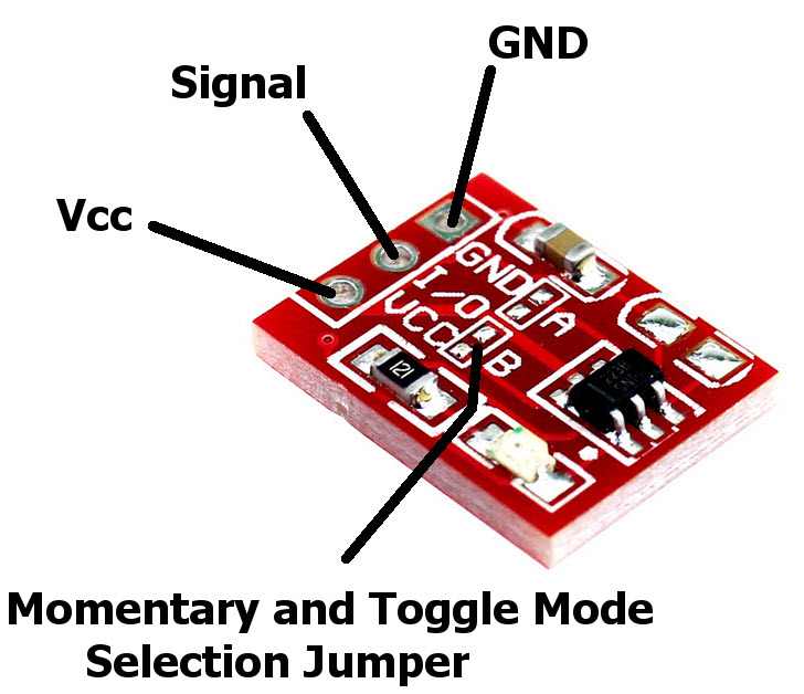
Capacitive Touch Board description
The board works well with 3.3v and 5v Systems, thus giving you the flexibility to use it straight away, these boards comes with onboard LED for the indication, thus you can use it as an independent product without any need of Microcontroller or Microprocessor. Now, refer the breadboard connection for the Capacitive touch board and the LED:
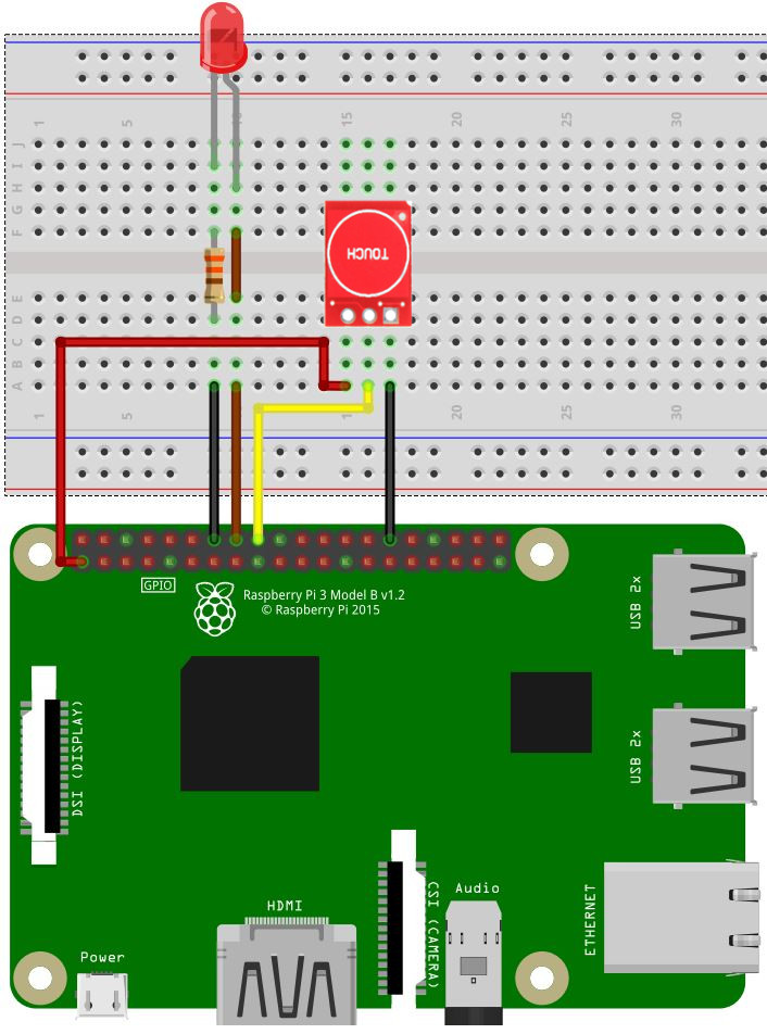
Capapcitive Touch and LED Connection with Raspberry Pi
Since we had replaced the tactile switch with Capacitive touch module in this circuit and we let the LED stay as it is like in the previous steps, thus the code which we used to control LED with tactile switch will work for this module as well.
Note: We had used GPIO pin 24 to connect Signal pin of the Capacitive touch module thus the previous code will work for this case as well, but if you had used some other pins for this module, make sure to change the pin numbering in the code as well.
If you are using the Capacitve module in Toggle Mode, try out the following code to understand the difference:
|
|
Transistor and Buzzer
Till now, you have seen the LED indication in the output side, now its time to add some sound to the circuit, since you had already worked with ” Getting started with switch, transistors and buzzer on breadboard “ tutorial, this step is going to be easy. Refer the modified breadboard connection for the circuit.
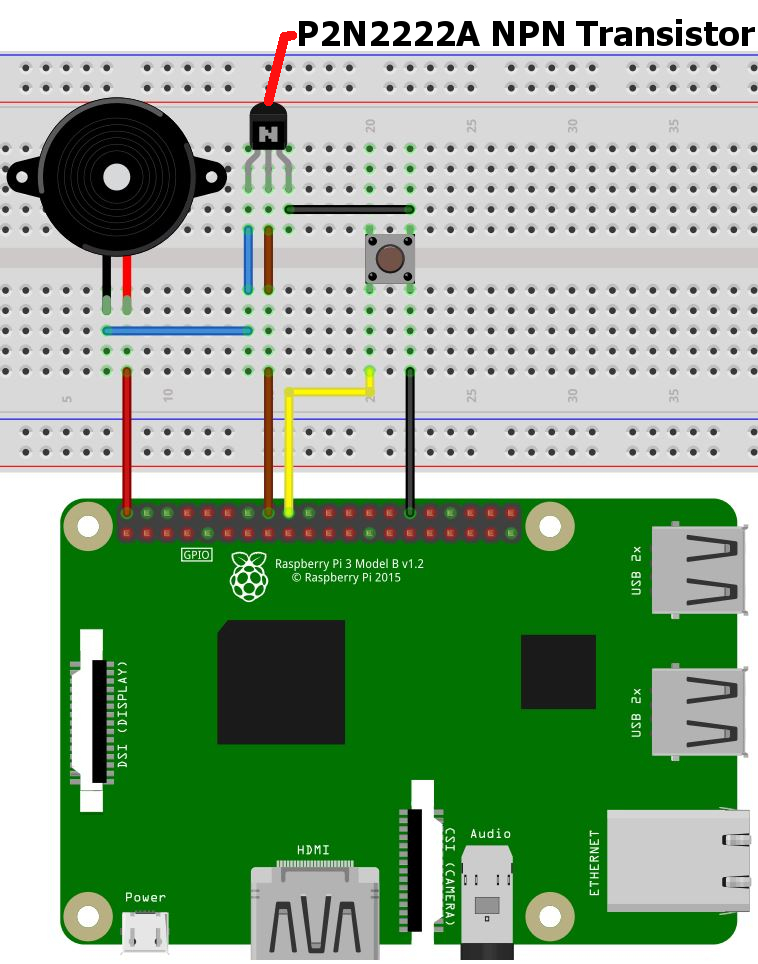
Transistor, Buzzer and Switch Interface with Raspberry Pi
We are not adding any specific code to this section because the circuit is connected to work with all the three codes described above, so we will recommend you to run all the three codes again for the above circuit, try to add and change the delay in the code, so that you can hear the variation in the output.Since you already understood the basics of various components and its interfacing and programming in scratch and python, we are giving you challenge to breadboard RGB LED we provided in the Kit and write your own Python and Scratch code for the same, to made it glow for different combination of colors.
Let us know your feedback on this and we are happy to help you, if you found any issue or difficulty in any circuit or have any queries, please do let us know.