Tutorial: How to Breadboard LED
Heard of breadboard? Sure you do, but some of you don’t have much idea that, what this little piece can do, we will start with some of the basics of breadboards before we start with projects. Breadboards are one of the basic element when you start learning how to build circuits. Breadboards are preferred platform to start building circuits because it don’t need any soldering, thus giving you the flexibility to try, test and modify your circuit at any point of time. They allow you to make quick circuits, test out ideas and allow prototyping before making a permanent Printed Circuit Board. They are inexpensive and reusable and they are easily available in any electronics store.
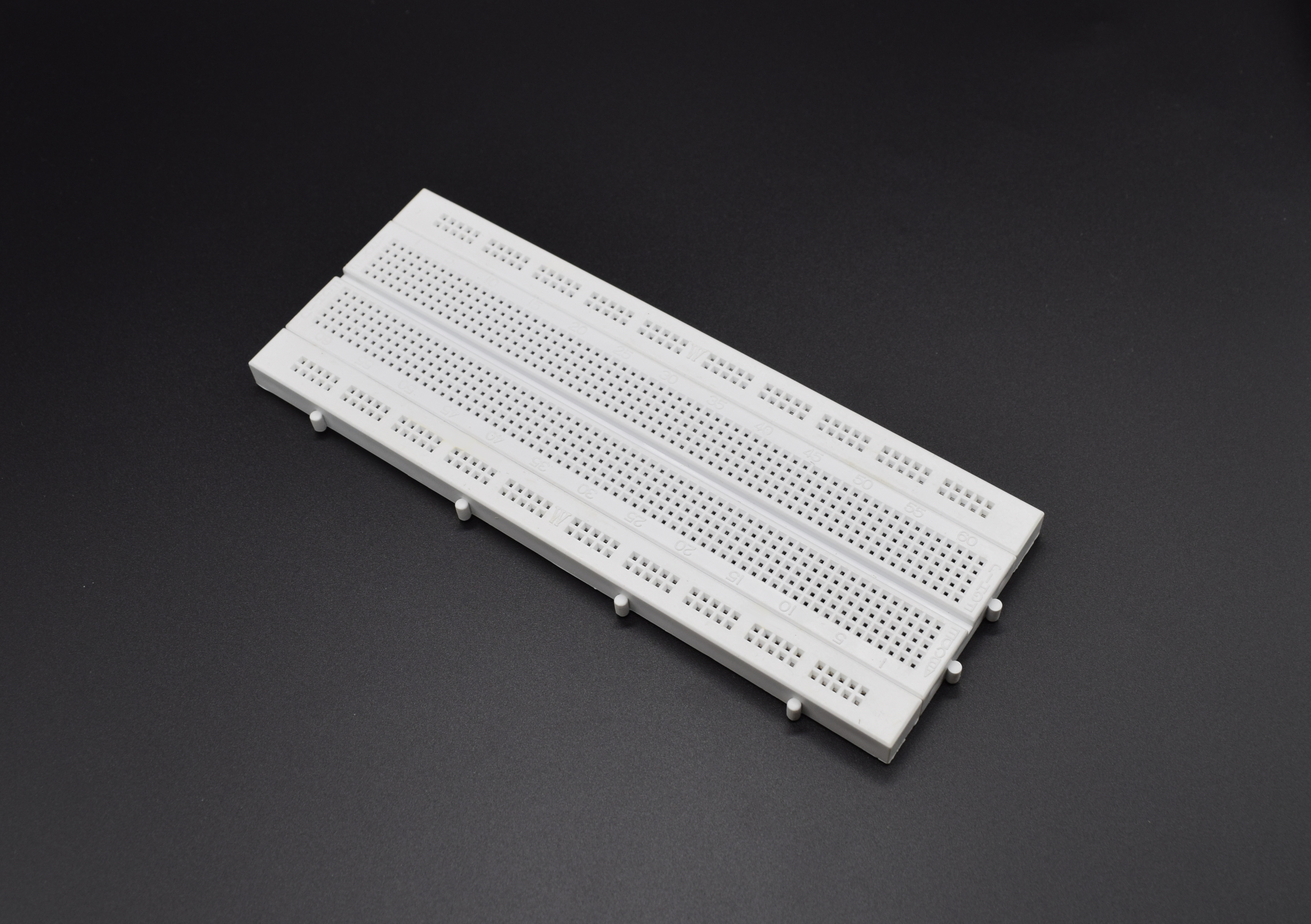
Breadboard is nothing but a plastic base with lots of holes in it, where you can fit in your components and wires to build your circuit. You can’t see what’s going inside the breadboard, but inside its nothing but many strips of metal that connect the rows and columns together. These metal strips are springy so that when you poke a wire or component into the hole, the clips grab onto it.
Breadboards are used for both the simplest circuit as well as very complex circuits. In case one breadboard can’t accommodate your circuit, you can snap in multiple breadboards together to make a big breadboard base. You can use breadboard to test and figure out the working of Integrated circuits (ICs).
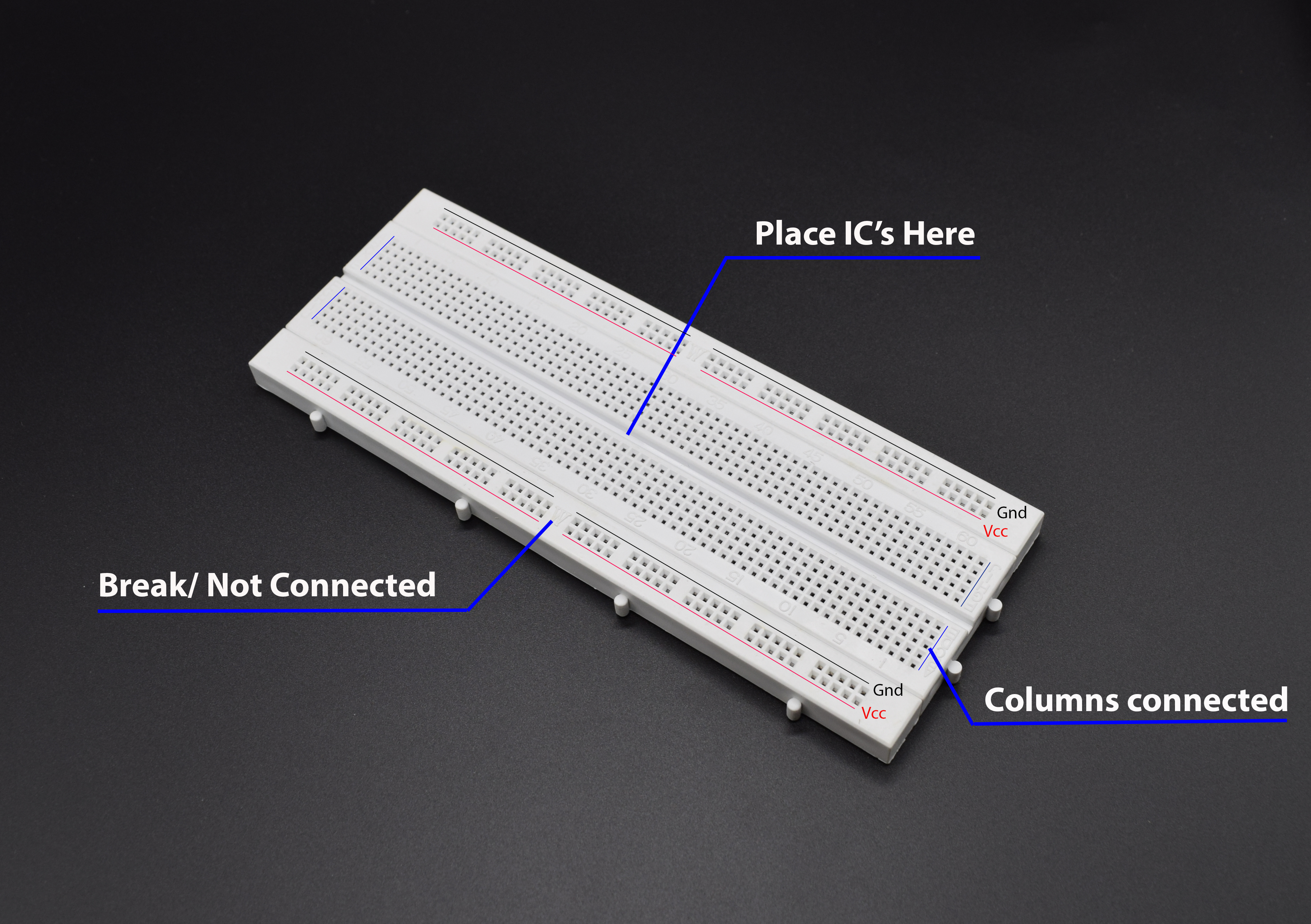
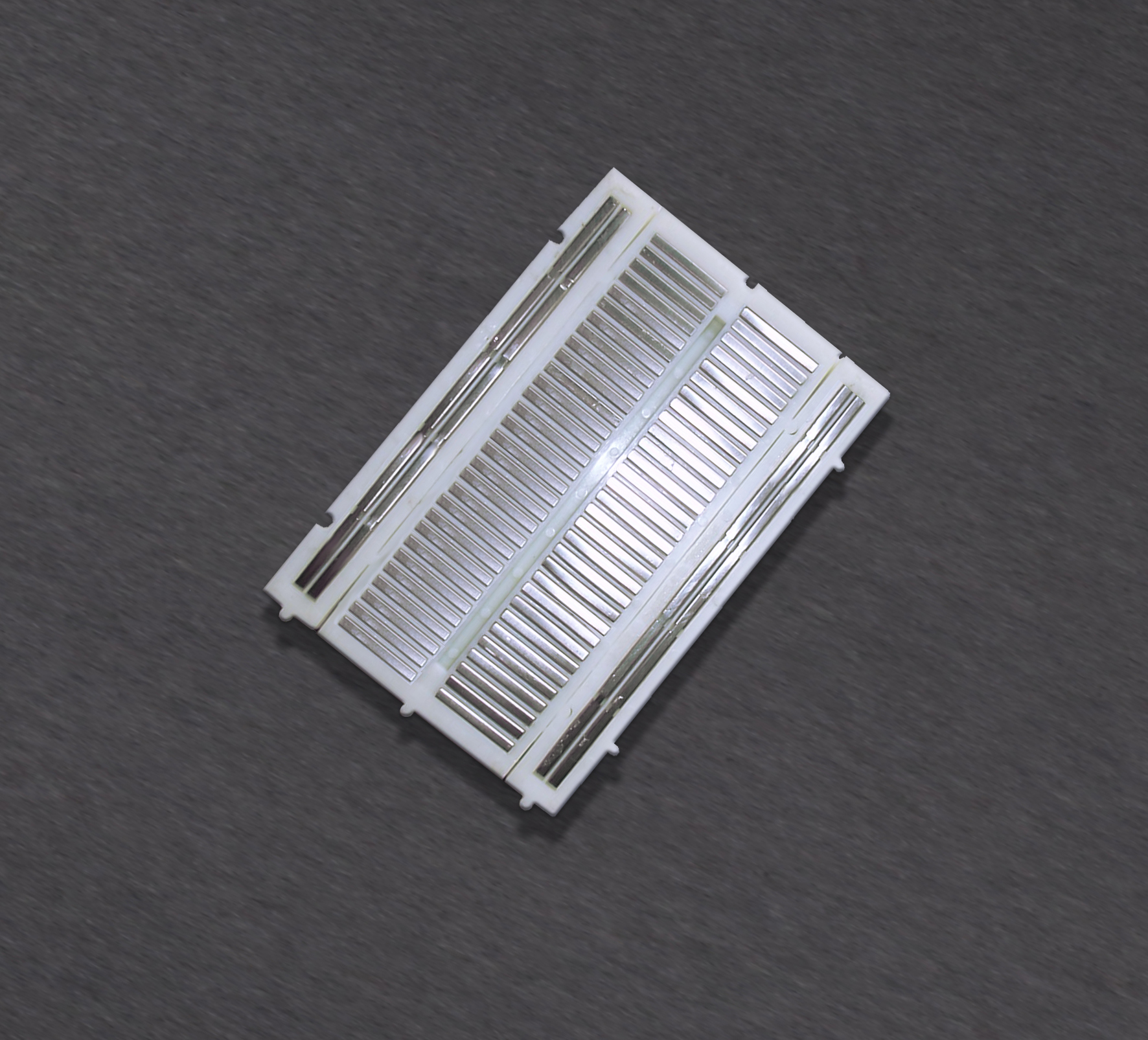
If you refer the description in the image above you can see that the how tracks are connected inside the breadboard. Refer the Vcc and Gnd Lines in the image above, you can see these two lines are running round the borders, thus allowing us to use these lines for power supply distribution, but there is a discontinuity in Vcc and Gnd tracks as shown above(mentioned “Not Connected”), which you need to connect with jumpers to distribute the power. The center holes are column connected as shown in the picture and there is a gap in between the same columns, allowing us to fit in IC to the gap. To make things further clear, we have added the tear down image of the breadboard, refer the next diagram to get better idea of inside connections.
The image shown above is of Half sized breadboard, thus don’t be confused comparing it with previous images. Hope things are clear to this point and you understood the breadboard well, now we will move further and see how to start building basic circuits on this breadboard. We are going to start with LED circuit, which is common to all the devices, we are going to build a circuit for Power LED Indication, i.e whenever there is power in the circuit, this led will let us know about it.

If you notice the above image you will see the legs of LED mentioned with Anode and cathode and to understand how to distinguish between anode and cathode pins, we provided hints in the image, its nothing but one cut mark(Means the LED is not completely round from the bottom side) which indicates that the leg underneath it is cathode(-ve) pin and if we seen the size of the legs, the anode(+ve) pin is little longer. But most of the times you have to trim the legs of LED when you use these LED in any circuit thus making the anode pins and cathode pins indistinguishable in terms of Leg size.
The importance of anode and cathode pins in LED is that, LED will glow only is you provide +ve power supply to Anode pin and –ve power supply to Cathode Pin. But wait, you cannot straight away supply the LED with power supply because there are chances that more current will pass through LED and this will lead to damage the LED, to avoid this situation, it is strongly recommended to use the resistor along with LED.
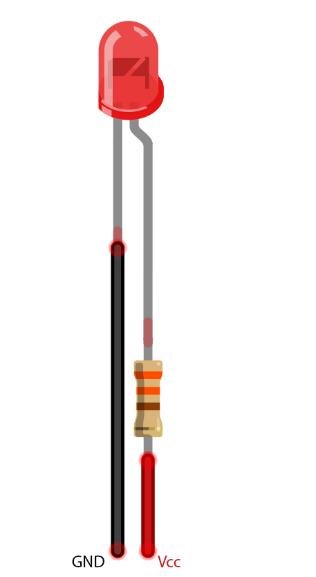
The circuit will be something like shown above. But it is really important to use the correct resistor value in the circuit to limit the current. We will show you how to select the correct resistor value for each circuit. For this, you need to understand two necessary parameters of LED, i.e LED Current and LED Forward voltage, refer the section below, for detailed description:
LED Current:
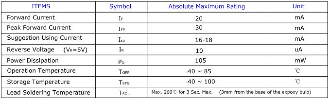
As an example we will refer the datasheet for Basic Red 5mm LED.Starting at the top and making our way down, the first thing we encounter is this Absolute maximum ratings table:
Confused? Questions coming that what does it all mean? right ?
So, the first row in the table indicates how much current your LED will be able to handle continuously. In this case, you can give it 20mA or less, and it will shine its brightest at 20mA. The second row tells us what the maximum peak current should be for short bursts. This LED can handle short bumps to 30mA, but you don’t want to sustain that current for too long. This datasheet is even helpful enough to suggest a stable current range (in the third row from the top) of 16-18mA. That’s a good target number to help you make the resistor calculations we talked about.
The following few rows are of less importance for the purposes of this tutorial. The reverse voltage is a diode property that you shouldn’t have to worry about in most cases. The power dissipation is the amount of power in milliWatts that the LED can use before taking damage. This should work itself out as long as you keep the LED within its suggested voltage and current ratings.
LED Forward Voltage
Now, when you check the datasheet further, you will come across the next table shown as follows:
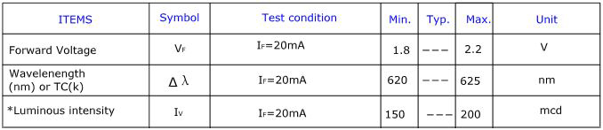
Now,this is a useful little table! The first row tells us what the forward voltage drop across the LED will be. Forward voltage is a term that will come up a lot when working with LEDs. This number will help you decide how much voltage your circuit will need to supply to the LED.You need to follow the following formula every time you build circuits something with LED, refer the section below:
The basic ohm’s law states that:
V = I x R or R = V/I
where,
V = Supply Voltage
I = Current through LED
R = Circuit Resistor
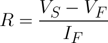
Thus, applying this law for LED circuit, we will get following formula:
Where,
VS = Source voltage (usually a battery or power supply voltage)
VF = LED’s forward voltage
IF = Desired current that runs through it.
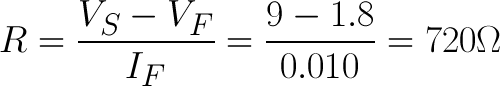
For example, assume in this example you have a 9V battery to power an LED. If your LED is red, it might have a forward voltage around 1.8V. If you want to limit the current to 10mA (or 0.010A) rather than limiting it to 20mA , use a series resistor of about 720Ω.
Now, if we are going to build power supply Indicator circuit for 5v system, thus our resistor calculation will come somewhat like this:
R = (5-1.8)V ÷ 0.010A
R = 3.2V ÷ 0.010 A
R = 320 V/A
R = 320 Ω
R = 330Ω Approx (Nearest standard resistor value)
Thus if you notice in the circuit shown above, you will see that we had used 330Ω resistor in the circuit, but wait you may be confused with how the resistor shown above is 330Ω, its again you need to follow the ring colors on the resistor surface. Refer the image below for better idea:
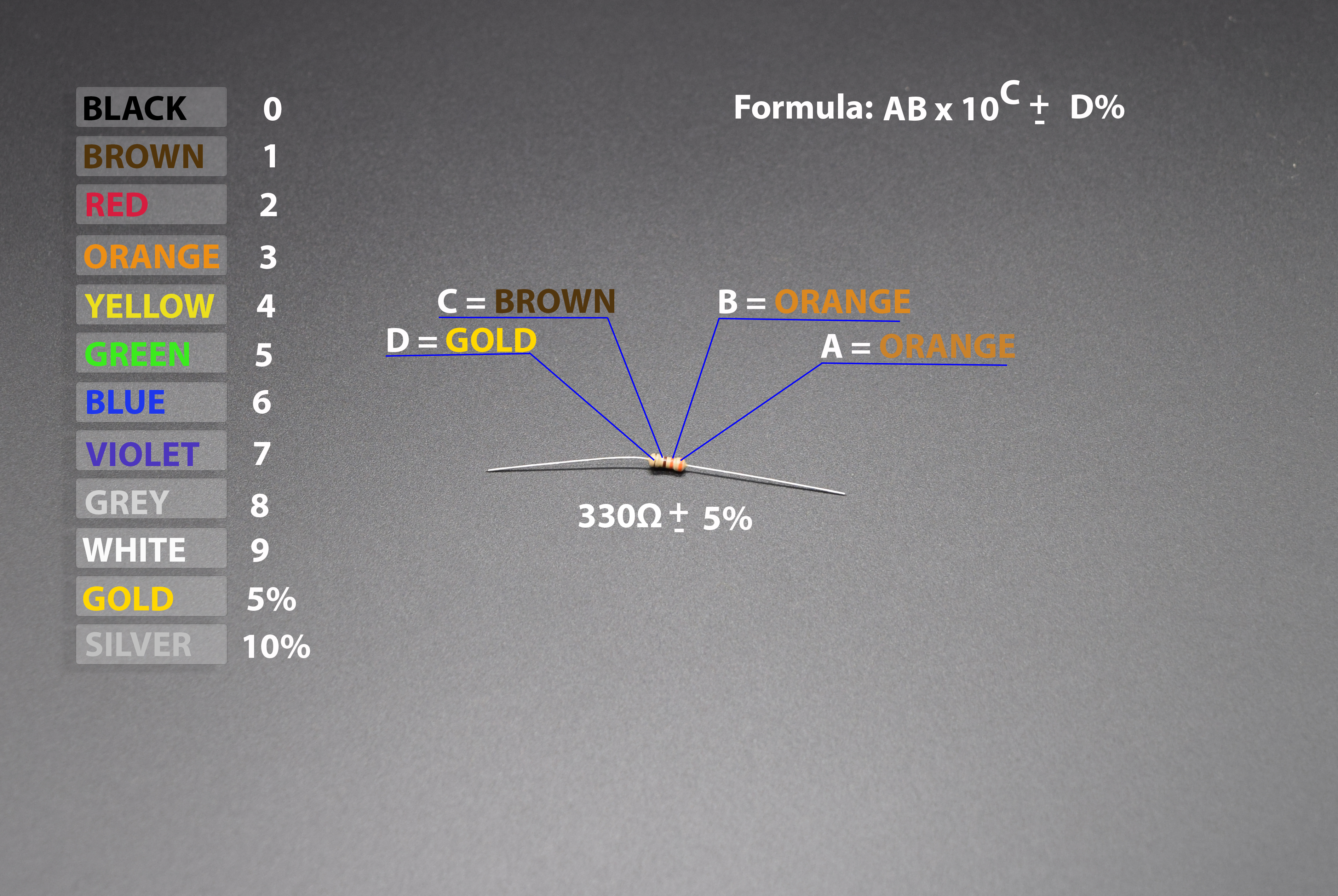
If you notice in the image, it is well documented how the 330Ω value is calculated. Refer the formula shown on the image, which will help you to find out the resistance value of the resistor, you just need to substitute the A,B,C and D value in the formula based on the colored ring.
In our case the resistor colors are orange, orange, brown, gold in sequence, thus if we substitute the corresponding values of the colors in the formula, yow will get: 33 x 10, which is nothing but 330 with 5% tolerance, tolerance will let you know how good the resistor is?
In this case its 5% means: The resistance value is limited within the vast range [270 – (5% of 270)] and [270 + (5% of 270)], which is not good, the lesser the range, the more close the resistance to the desired resistance value.
Let start assembling the circuit in the breadboard, refer the image below for better idea:
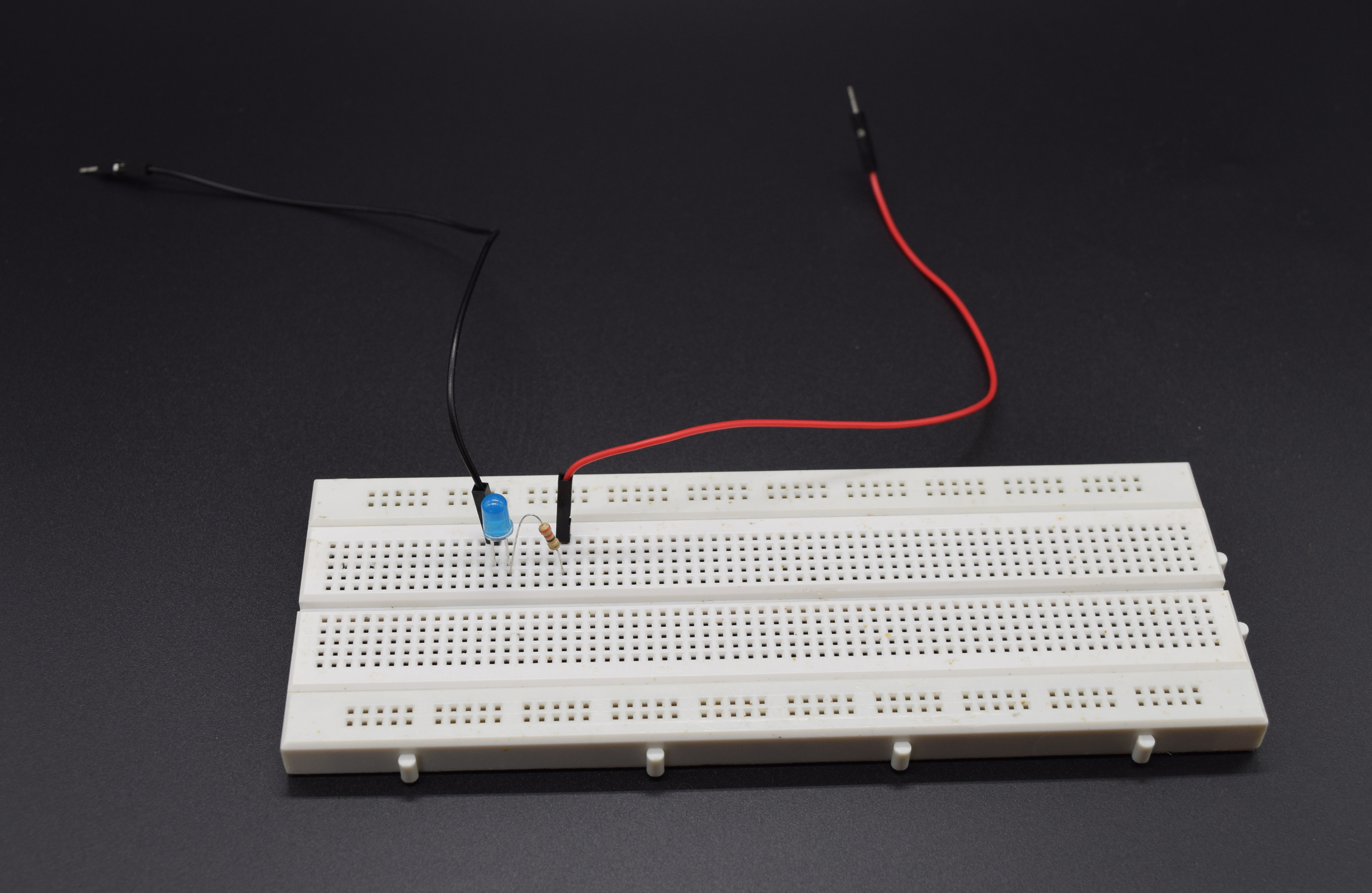
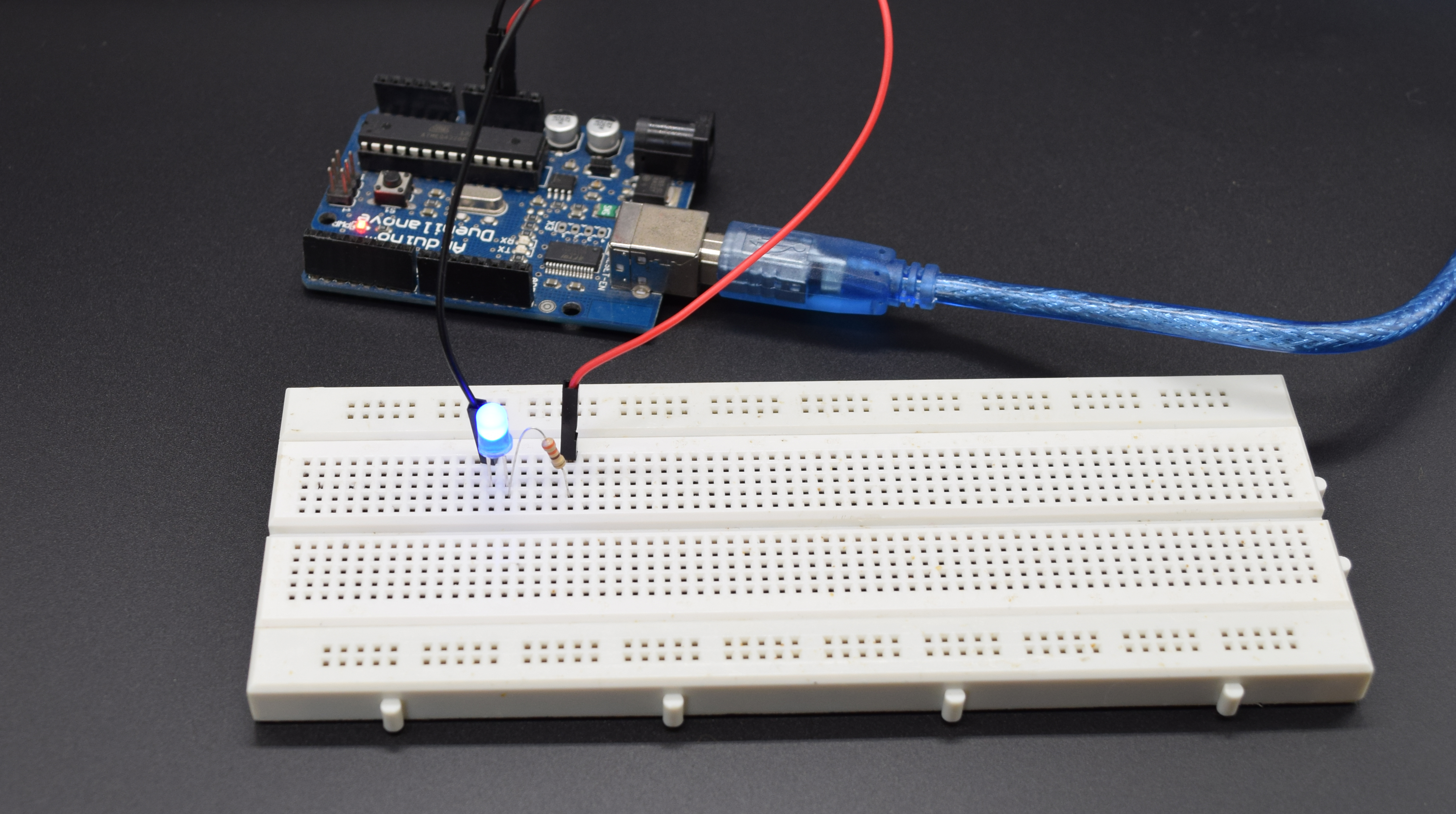
Now, you can see how we utilized the breadboard columns which are internally shorted to connect the LED anode pin with resistor, similarly we used the jumper wires to connect the LED cathode pin and resistor other end. Now if you power the above shown circuit, i.e Red wire with 5v and Black with Ground supply, you will see that your LED will glow safely.
Note: We had Connected 5v supply and GND from Arduino board in the following image, you can use Raspberry Pi or any other boards you having with you to supply 5v and GND from the board. If you having our Raspberry Pi Electronics Starter kit with you, then you can use the RasPiO Portplus we provided with the kit, to find the 5v and GND pins on Raspberry Pi and use the Male-Female Jumper wire we provided in the Kit to Supply power to the LED on breadboard.
Now, we want you to build one circuit on your own with multiple LED’s in series, but before doing that, we want to clear some basics related to building such circuits. When you went through LED forward voltage section above, you seen the table with LED forward voltage, you must use that value to find out how much LED you can use in your circuit. When using multiple LED’s in series, always remember that the Forward Voltage of all of your LEDs added together can’t exceed your system voltage. This is because every component in your circuit has to share the voltage, and the amount of voltage that every part uses together will always equal the amount that’s available. This is called Kirchhoff’s Voltage Law. So if you have a 9V power supply and each of your LEDs have a forward voltage drop of 2.4V then you can’t power more than three at a time.
Kirchhoff’s Laws also come in handy when you want to approximate the voltage across a given part based on the Forward Voltage of other parts. For instance, in the example we just mentioned there’s a 9V supply and 3 LEDs with a 2.4V Forward Voltage Drop each. Of course we would want to include a current limiting resistor, right? How would you find out the voltage across that resistor? It’s easy:
9 (System Voltage) = 2.4 (LED 1) + 2.4 (LED 2) + 2.4 (LED 3) + Resistor
9 = 7.2 + Resistor
Resistor = 9 – 7.2
Resistor = 1.8
So there is 1.8V across the resistor! This is a simplified example and it isn’t always this easy, but hopefully this gives you an idea of why Forward Voltage Drop is important. Using the voltage number you derive from Kirchhoff’s Laws you can also do things like determine the current across a component using Ohm’s Law. In short, you want your system voltage equal to the expected forward voltage of your combined circuit components.
Hope the things are more clear to you now and this is the end of your first basic steps towards hands on with electronics. Refer the next tutorial for more advanced Projects.
However, after this lesson, you’ll be more on your own to figure out how to connect up the standard breadboard, OK?
Use flexible jumper wires to jump from the breadboard to other components such as an Arduino or Raspberry Pi. The flexible wires will allow you greater flexibility when moving your boards around or re-configuring.