Micro OLED Hookup guide for ESP8266 and Particle Photon
Introduction to Micro OLED Display
An organic light-emitting diode (OLED) is a light-emitting diode (LED) in which the emissive electroluminescent layer is a film of organic compound that emits light in response to an electric current. This layer of organic semiconductor is situated between two electrodes typically and at least one of these electrodes is transparent.
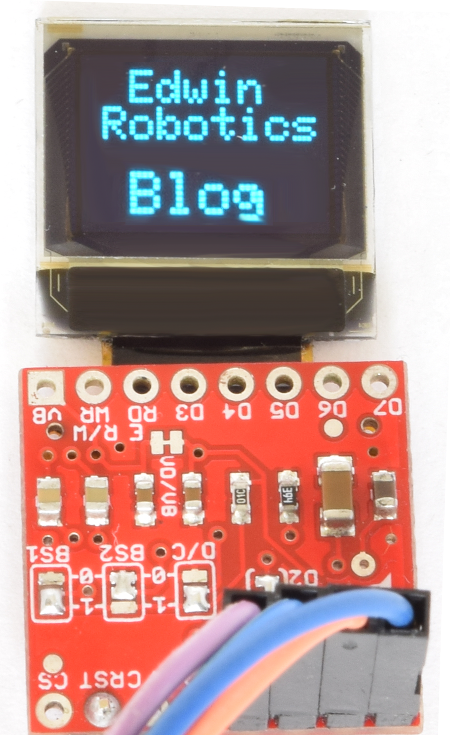
The Micro OLED Display used in this tutorial is a small monochrome, blue-on-black OLED. It’s 64 pixels wide and 48 pixels tall, measuring 0.66″ across. It’s micro sized and sufficient enough to fit a deceivingly large amount of graphics on there. this Micro OLED is easy to control over either an SPI or I2C interface.
Sparkfun have the breakout board for this display, its easy and time saving to use the same breakout for any projects.This Micro OLED Breakout provides access to 16 of the OLED’s pins. This breakout board operates at 3.3V with a current of 10mA (20mA max).The Micro OLED present in this breakout is same as Display used in the SparkFun MicroView – OLED Arduino Module.
The breakout board is an open source design and you can get the design files here
Display board Features:
- Operating Voltage: 3.3V
- Screen Size: 64×48 pixels (0.66″ Across)
- Monochrome Blue-on-Black
- SPI or I2C Interface
OLED Pin Reference:
Pin Label SPI Function I2C Function Notes GND Ground Ground 0V 3V3 (VDD) Power Power Should be a regulated 3.3V supply. D1 (SDI) MOSI SDA Serial data in D0 (SCK) SCK SCL SPI and I2C clock D2 (SDO) MISO — Can be unused in SPI mode. No function for I2C. D/C Data/Command I2C address selection Digital pin to signal if incoming byte is a command or screen data. RST Reset Reset Active-low screen reset. CS CS — SPI chip select (active-low)
Sparkfun has provided detailed hookup guide on their blog to setup the OLED breakout board.Follow the links below to see the detailed Instructions.
- Breakout Board Overview
- Hardware Assembly
- Hardware Hookup
- Arduino Library Download, Install, and Test
- Using the Arduino Library
When we tested the board with Sparkfun library we faced some issue with displaying text, thus we made changes to library and sorted out the issue. The library is available to download from GitHub, Click here to download the library.
When you use this Library, make sure you either replace the Sparkfun library or remove and make a backup of the Sparkfun library from the Arduino.
The hookup guide to setup the Micro OLED display with different boards can be found below:
Micro OLED Breakout Hookup with ESP8266
The ESP8266 is a low-cost Wi-Fi chip with full TCP/IP stack and Microcontroller capability produced by Shanghai-based Chinese manufacturer, Espressif. There are many third party modules With ESP8266 available in the market and you can decide which one suits best for your application, we are using the Sprakfun ESP8266 Thing in this tutorial.
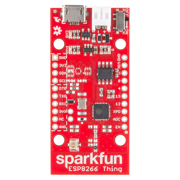
The SparkFun ESP8266 Thing is a breakout and development board for the ESP8266 WiFi SoC – a leading platform for Internet of Things (IoT) or WiFi-related projects. These are some features of the board:
ESP8266 Thing Features:
- All module pins broken out
- On-board LiPo charger/power supply
- 802.11 b/g/n
- Wi-Fi Direct (P2P), soft-AP
- Integrated TCP/IP protocol stack
- Integrated TR switch, balun, LNA, power amplifier and matching network
- Integrated PLLs, regulators, DCXO and power management units
- Integrated low power 32-bit CPU could be used as application processor
- +19.5dBm output power in 802.11b mode
- Arduino IDE integration
- Breadboard Compatible Breakout Headers position
- Power On-Off Switch
- Status LED
- Operating Voltage: 3.3v
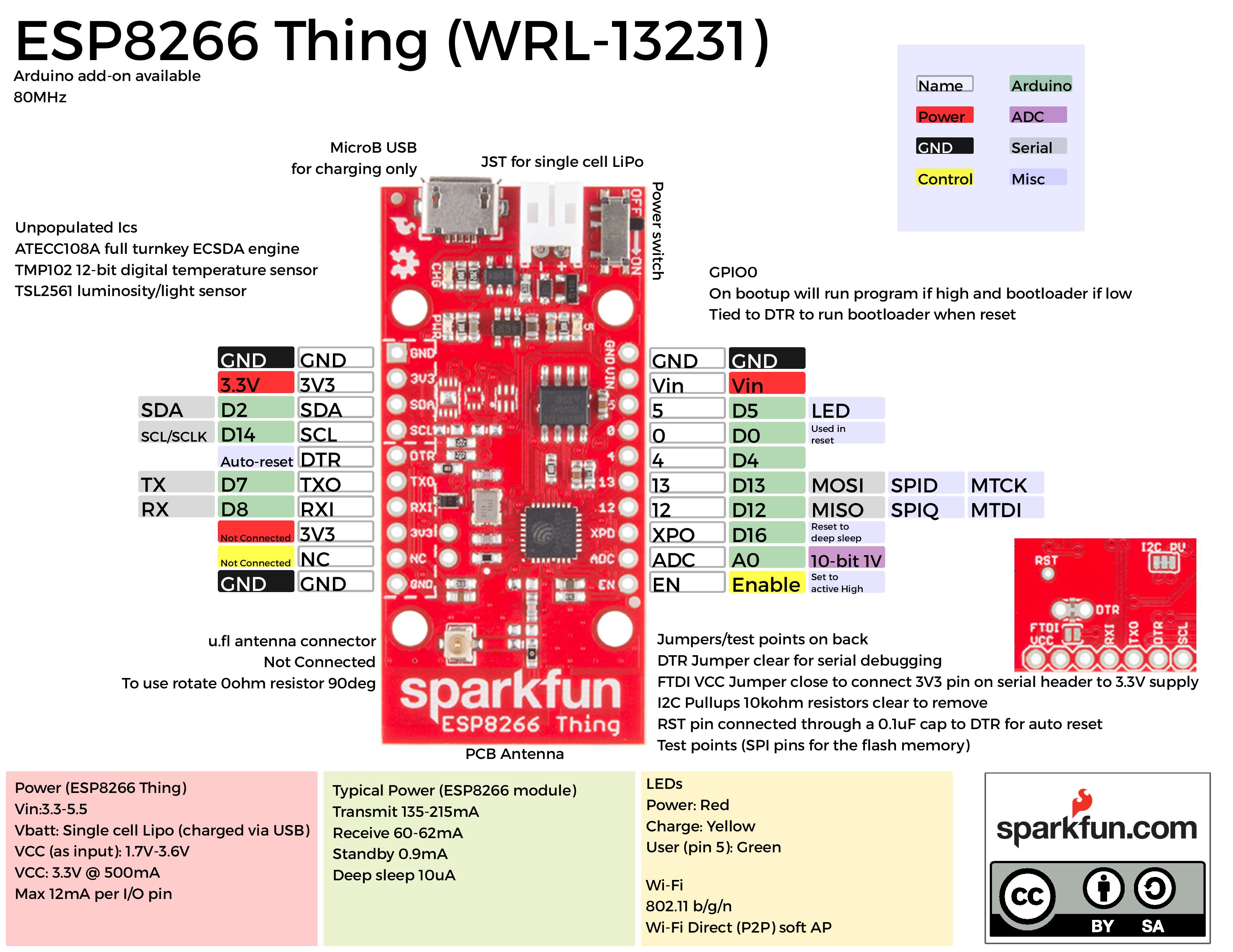
Refer the Graphical Datasheet for hardware description
Programming the Thing:
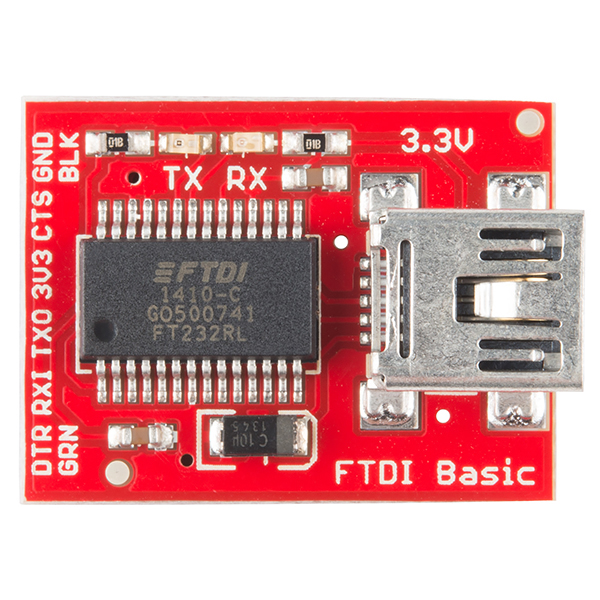
The ESP8266 has a built-in serial bootloader, which allows for easy programming and re-programming. You don’t need a specialized, expensive programmer – just a simple, USB-to-Serial converter.
We use a 3.3V FTDI Basic to program the Thing, but other serial converters with 3.3V I/O levels should work. The converter does need a DTR line in addition to the RX and TX pins.The FTDI Basic’s 6-pin header matches up exactly to the Thing’s 6-pin serial port header. To set up for programming, simply connect the FTDI directly to this port – take care to match up the DTR and GND pins!
Note: While programming the Thing, it’s best to power it off USB. We’ve noticed programming is more likely to fail if the Thing is only powered via the battery.
Now we will see how to connect the ESP8266 Thing with Micro OLED Breakout in I2C Mode:
- Setup the jumpers in the Hardware
Setting Jumpers for I2C Mode:
- Short D1/D2 – This will combine the data output line and data input line into one.
- Set BS1 to 1 – The BS1 jumpers comes defaulted to 0, which does half the job of setting it to SPI. To set the display to I2C, you’ll need to flip that jumper to 1. Also make sure the BS2 jumper remains set to 0.
- Set D/C – In I2C mode, the D/C pin configures the display’s 7-bit address. You can set it to either 0 or 1, just keep that value in mind when you get to the code part of this tutorial.
Once you’re done setting jumpers, the back of the board should look a little something like this:

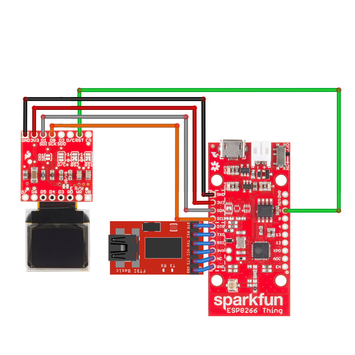
Follow the above shown connections for I2C interface between OLED and ESP8266 Thing. Any Digital pin can be connected to RST(Reset) Pin of OLED, we used Pin number 5 from the ESP8266 Thing.
Note: Pin 5 on the ESP8266 Thing is connected to onboard LED, we tampered the tracks to LED to disable it.
Try out the following code on the ESP8266 Things and check whether your board is working fine or not, We used the modified library (The link to download the library is mentioned above), make sure you must use the same to made it work.
#include <Wire.h> //Include Wire if you’re using I2C
//#include <SPI.h> // Include SPI if you’re using SPI
#include <ER_MicroOLED.h> // Include the ER_MicroOLED library
#define PIN_RESET 5 // Connect RST to pin 9 (req. for SPI and I2C)
//#define PIN_DC 8 // Connect DC to pin 8 (required for SPI)
//#define PIN_CS 10 // Connect CS to pin 10 (required for SPI)
#define DC_JUMPER 1
// Also connect pin 13 to SCK and pin 11 to MOSI
// Declare a MicroOLED object. The parameters include:
// 1 – Reset pin: Any digital pin
// 2 – D/C pin: Any digital pin (SPI mode only)
// 3 – CS pin: Any digital pin (SPI mode only, 10 recommended)
//MicroOLED oled(PIN_RESET, PIN_DC, PIN_CS);
MicroOLED oled(PIN_RESET, DC_JUMPER); // Example I2C declarationvoid setup()
{
oled.begin();// clear(ALL) will clear out the OLED’s graphic memory.
// clear(PAGE) will clear the Arduino’s display buffer.
oled.clear(ALL); // Clear the display’s memory (gets rid of artifacts)
// To actually draw anything on the display, you must call the
// display() function.
oled.display();
delay(2000);oled.clear(PAGE);
oled.clear(ALL);
oled.setCursor(0,0);
oled.setTextColor(WHITE);
oled.setTextSize(0);oled.println(“hello !!!!”);
oled.display();
}void loop()
{
//oled.line(x0, y0, x1, y1); // Draw a line from (x0,y0) to (x1,y1);
oled.line(5, 15, 57, 15); // Draw a line from (x0,y0) to (x1,y1);//oled.rect(x0, y0, width, height); // Draw a rectange from (7,5) to (31,18)
oled.rect(5, 20, 52, 20); // Draw a rectange from (7,5) to (31,18)oled.line(5, 45, 57, 45); // Draw a line from (x0,y0) to (x1,y1);
//oled.rectFill(7, 5, 35, 5); // Fill a rectangle from (7, 5) to (42, 10)
oled.rectFill(10, 25, 42, 10); // Fill a rectangle from (7, 5) to (42, 10)//oled.circleFill(42, 20, 7); // Fill a circle, 7 radius, centered at (42, 20)
oled.display(); // Draw to the screen
}
Micro OLED Hookup with Particle Photon
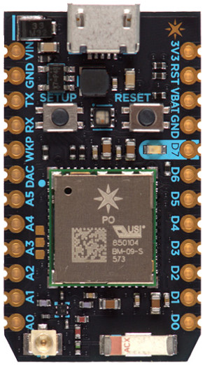
The Photon is a development kit for creating Wi-Fi connected products. It’s based on Broadcom’s WICED architecture, and combines a powerful STM32 ARM Cortex M3 microcontroller and a Broadcom Wi-Fi chip (the same one that’s in Nest Protect, LIFX, and Amazon Dash).
Photon Features:
- Fits in a standard breadboard (with headers)
- Surface mountable for machine assembly (without headers)
- Backwards compatible with the Spark Core
- Broadcom BCM43362 Wi-Fi chip
- STM32F205 120Mhz ARM Cortex M3
- 1MB flash, 128KB RAM
- 802.11b/g/n
- FCC/CE/IC certified
- Open source hardware
- On-board RGB status LED (ext. drive provided)
- 18 Mixed-signal GPIO and advanced peripherals
- Real-time operating system (FreeRTOS)
- Soft AP setup
| Peripheral Type | Qty | Input(I) / Output(O) | FT[1] / 3V3[2] |
|---|---|---|---|
| Digital | 18 | I/O | FT/3V3 |
| Analog (ADC) | 8 | I | 3V3 |
| Analog (DAC) | 2 | O | 3V3 |
| SPI | 2 | I/O | 3V3 |
| I2S | 1 | I/O | 3V3 |
| I2C | 1 | I/O | FT |
| CAN | 1 | I/O | FT |
| USB | 1 | I/O | 3V3 |
| PWM | 9[3] | O | 3V3 |
Notes:
[1] FT = 5.0V tolerant pins. All pins except A3 and DAC are 5V tolerant (when not in analog mode). If used as a 5V input the pull-up/pull-down resistor must be disabled.
[2] 3V3 = 3.3V max pins.
[3] PWM is available on D0, D1, D2, D3, A4, A5, WKP, RX, TX with a caveat: PWM timer peripheral is duplicated on two pins (A5/D2) and (A4/D3) for 7 total independent PWM outputs. For example: PWM may be used on A5 while D2 is used as a GPIO, or D2 as a PWM while A5 is used as an analog input. However A5 and D2 cannot be used as independently controlled PWM outputs at the same time.
Photon Graphical Pin Description:
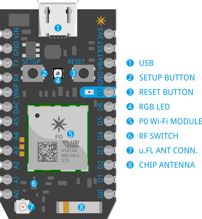
Click here to see the Complete Datasheet for Particle Photon.
To hookup the OLED with Photon in I2C mode is pretty much same as what we seen with ESP8266 Thing except this point that both the SDA and SCL lines must be pulled high always. Refer the connection diagram for better idea.
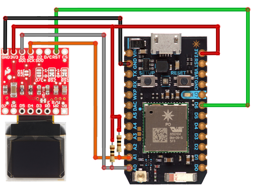
Pullup is the thing you need to take care of, we used 10kΩ Resistor for pullup and connected it to 3v3 supply line as shown in the figure.
Programme the Particle Photon:
Photon can be programmed in three ways:
- Particle Build(Online)
- Particle Dev(Half Online, Half Offline)
- ARM GCC and the DFU Bootloader (Offline)
We recommend you to start with Particle Build(Online), the Particle Build IDE is an always-online, browser-based portal where your Photon code can be edited, saved, and shared. This cloud-based IDE handles code compilation and flashes the built binaries to your Photon over-the-air. You don’t even need your Photon next to you to update its program!
To load the Build IDE head over to build.particle.io.
Sparkfun has provided more detailed Instructions for the beginners to understand the IDE better, Click here to see the Particle Build(Online) guide.
Similarly they provided instruction to understand Particle Dev(Half Online, Half Offline) guide and ARM GCC and the DFU Bootloader (Offline) guide.
To run the OLED program in the Particle Build(online), follow these steps:
- Add your device to the Particle Build.
- Download Particle Mobile App to your Handset- iPhone | Android
- Open the app on your phone. Log in or sign up for an account with Particle if you don’t have one.
- Use this Particle First time setup guide
- Open the online terminal build.particle.io and login in to your account
- Check under devices tab that whether your devices is listed or not, if not try to add it using mobile app.
- Goto ” code tab -> Create New App “
- Add micro OLED library to current App.
- To add Librbary, goto: ” Libraries Tab -> Community Library Search Box -> type OLED “
- There you will see SPARKFUNMICROOLED Library, Click ” Include in App ” option.
- Save the App using save option.
- Use the following code to begin with
/******************************************************************************
Micro-OLED-Shield-Example.ino
SparkFun Micro OLED Library Hello World Example
Jim Lindblom @ SparkFun Electronics
Original Creation Date: June 22, 2015This sketch prints a friendly, recognizable logo on the OLED Shield, then
goes on to demo the Micro OLED library’s functionality drawing pixels,
lines, shapes, and text.Hardware Connections:
This sketch was written specifically for the Photon Micro OLED Shield,
which does all the wiring for you. If you have a Micro OLED breakout,
use the following hardware setup:MicroOLED ————- Photon
GND ——————- GND
VDD ——————- 3.3V (VCC)
D1/MOSI —————– A5 (don’t change)
D0/SCK —————— A3 (don’t change)
D2
D/C ——————- D6 (can be any digital pin)
RST ——————- D7 (can be any digital pin)
CS ——————- A2 (can be any digital pin)Development environment specifics:
IDE: Particle Build
Hardware Platform: Particle Photon
SparkFun Photon Micro OLED ShieldThis code is beerware; if you see me (or any other SparkFun
employee) at the local, and you’ve found our code helpful,
please buy us a round!Distributed as-is; no warranty is given.
*******************************************************************************/
#include “SparkFunMicroOLED/SparkFunMicroOLED.h” // Include MicroOLED library
#include “math.h”//////////////////////////////////
// MicroOLED Object Declaration //
//////////////////////////////////
// Declare a MicroOLED object. If no parameters are supplied, default pins are
// used, which will work for the Photon Micro OLED Shield (RST=D7, DC=D6, CS=A2)
//MicroOLED oled;
MicroOLED oled(MODE_I2C, D6); // Example I2C declaration RST=D7, DC=LOW (0)//SYSTEM_MODE(MANUAL);
void setup()
{
Serial.begin(9600);
oled.begin(); // Initialize the OLED
oled.clear(ALL); // Clear the display’s internal memory
oled.display(); // Display what’s in the buffer (splashscreen)
delay(1000); // Delay 1000 ms
randomSeed(analogRead(A0) + analogRead(A1));
}void loop()
{
pixelExample(); // Run the pixel example function
lineExample(); // Then the line example function
shapeExample(); // Then the shape example
textExamples(); // Finally the text example
}void pixelExample()
{
printTitle(“Pixels”, 1);for (int i=0; i<512; i++)
{
oled.pixel(random(oled.getLCDWidth()), random(oled.getLCDHeight()));
oled.display();
}
}void lineExample()
{
int middleX = oled.getLCDWidth() / 2;
int middleY = oled.getLCDHeight() / 2;
int xEnd, yEnd;
int lineWidth = min(middleX, middleY);printTitle(“Lines!”, 1);
for (int i=0; i<3; i++)
{
for (int deg=0; deg<360; deg+=15)
{
xEnd = lineWidth * cos(deg * M_PI / 180.0);
yEnd = lineWidth * sin(deg * M_PI / 180.0);oled.line(middleX, middleY, middleX + xEnd, middleY + yEnd);
oled.display();
delay(10);
}
for (int deg=0; deg<360; deg+=15)
{
xEnd = lineWidth * cos(deg * M_PI / 180.0);
yEnd = lineWidth * sin(deg * M_PI / 180.0);oled.line(middleX, middleY, middleX + xEnd, middleY + yEnd, BLACK, NORM);
oled.display();
delay(10);
}
}
}void shapeExample()
{
printTitle(“Shapes!”, 0);// Silly pong demo. It takes a lot of work to fake pong…
int paddleW = 3; // Paddle width
int paddleH = 15; // Paddle height
// Paddle 0 (left) position coordinates
int paddle0_Y = (oled.getLCDHeight() / 2) – (paddleH / 2);
int paddle0_X = 2;
// Paddle 1 (right) position coordinates
int paddle1_Y = (oled.getLCDHeight() / 2) – (paddleH / 2);
int paddle1_X = oled.getLCDWidth() – 3 – paddleW;
int ball_rad = 2; // Ball radius
// Ball position coordinates
int ball_X = paddle0_X + paddleW + ball_rad;
int ball_Y = random(1 + ball_rad, oled.getLCDHeight() – ball_rad);//paddle0_Y + ball_rad;
int ballVelocityX = 1; // Ball left/right velocity
int ballVelocityY = 1; // Ball up/down velocity
int paddle0Velocity = -1; // Paddle 0 velocity
int paddle1Velocity = 1; // Paddle 1 velocity//while(ball_X >= paddle0_X + paddleW – 1)
while ((ball_X – ball_rad > 1) &&
(ball_X + ball_rad < oled.getLCDWidth() – 2))
{
// Increment ball’s position
ball_X+=ballVelocityX;
ball_Y+=ballVelocityY;
// Check if the ball is colliding with the left paddle
if (ball_X – ball_rad < paddle0_X + paddleW)
{
// Check if ball is within paddle’s height
if ((ball_Y > paddle0_Y) && (ball_Y < paddle0_Y + paddleH))
{
ball_X++; // Move ball over one to the right
ballVelocityX = -ballVelocityX; // Change velocity
}
}
// Check if the ball hit the right paddle
if (ball_X + ball_rad > paddle1_X)
{
// Check if ball is within paddle’s height
if ((ball_Y > paddle1_Y) && (ball_Y < paddle1_Y + paddleH))
{
ball_X–; // Move ball over one to the left
ballVelocityX = -ballVelocityX; // change velocity
}
}
// Check if the ball hit the top or bottom
if ((ball_Y <= ball_rad) || (ball_Y >= (oled.getLCDHeight() – ball_rad – 1)))
{
// Change up/down velocity direction
ballVelocityY = -ballVelocityY;
}
// Move the paddles up and down
paddle0_Y += paddle0Velocity;
paddle1_Y += paddle1Velocity;
// Change paddle 0’s direction if it hit top/bottom
if ((paddle0_Y <= 1) || (paddle0_Y > oled.getLCDHeight() – 2 – paddleH))
{
paddle0Velocity = -paddle0Velocity;
}
// Change paddle 1’s direction if it hit top/bottom
if ((paddle1_Y <= 1) || (paddle1_Y > oled.getLCDHeight() – 2 – paddleH))
{
paddle1Velocity = -paddle1Velocity;
}// Draw the Pong Field
oled.clear(PAGE); // Clear the page
// Draw an outline of the screen:
oled.rect(0, 0, oled.getLCDWidth() – 1, oled.getLCDHeight());
// Draw the center line
oled.rectFill(oled.getLCDWidth()/2 – 1, 0, 2, oled.getLCDHeight());
// Draw the Paddles:
oled.rectFill(paddle0_X, paddle0_Y, paddleW, paddleH);
oled.rectFill(paddle1_X, paddle1_Y, paddleW, paddleH);
// Draw the ball:
oled.circle(ball_X, ball_Y, ball_rad);
// Actually draw everything on the screen:
oled.display();
delay(25); // Delay for visibility
}
delay(1000);
}void textExamples()
{
printTitle(“Text!”, 1);// Demonstrate font 0. 5×8 font
oled.clear(PAGE); // Clear the screen
oled.setFontType(0); // Set font to type 0
oled.setCursor(0, 0); // Set cursor to top-left
// There are 255 possible characters in the font 0 type.
// Lets run through all of them and print them out!
for (int i=0; i<=255; i++)
{
// You can write byte values and they’ll be mapped to
// their ASCII equivalent character.
oled.write(i); // Write a byte out as a character
oled.display(); // Draw on the screen
delay(10); // Wait 10ms
// We can only display 60 font 0 characters at a time.
// Every 60 characters, pause for a moment. Then clear
// the page and start over.
if ((i%60 == 0) && (i != 0))
{
delay(500); // Delay 500 ms
oled.clear(PAGE); // Clear the page
oled.setCursor(0, 0); // Set cursor to top-left
}
}
delay(500); // Wait 500ms before next example// Demonstrate font 1. 8×16. Let’s use the print function
// to display every character defined in this font.
oled.setFontType(1); // Set font to type 1
oled.clear(PAGE); // Clear the page
oled.setCursor(0, 0); // Set cursor to top-left
// Print can be used to print a string to the screen:
oled.print(” !\”#$%&'()*+,-./01234″);
oled.display(); // Refresh the display
delay(1000); // Delay a second and repeat
oled.clear(PAGE);
oled.setCursor(0, 0);
oled.print(“56789:;<=>?@ABCDEFGHI”);
oled.display();
delay(1000);
oled.clear(PAGE);
oled.setCursor(0, 0);
oled.print(“JKLMNOPQRSTUVWXYZ[\\]^”);
oled.display();
delay(1000);
oled.clear(PAGE);
oled.setCursor(0, 0);
oled.print(“_`abcdefghijklmnopqrs”);
oled.display();
delay(1000);
oled.clear(PAGE);
oled.setCursor(0, 0);
oled.print(“tuvwxyz{|}~”);
oled.display();
delay(1000);// Demonstrate font 2. 10×16. Only numbers and ‘.’ are defined.
// This font looks like 7-segment displays.
// Lets use this big-ish font to display readings from the
// analog pins.
for (int i=0; i<25; i++)
{
oled.clear(PAGE); // Clear the display
oled.setCursor(0, 0); // Set cursor to top-left
oled.setFontType(0); // Smallest font
oled.print(“A0:”); // Print “A0”
oled.setFontType(2); // 7-segment font
oled.print(analogRead(A0)); // Print a0 reading
oled.setCursor(0, 16); // Set cursor to top-middle-left
oled.setFontType(0); // Repeat
oled.print(“A1:”);
oled.setFontType(2);
oled.print(analogRead(A1));
oled.setCursor(0, 32);
oled.setFontType(0);
oled.print(“A7:”);
oled.setFontType(2);
oled.print(analogRead(A7));
oled.display();
delay(100);
}// Demonstrate font 3. 12×48. Stopwatch demo.
oled.setFontType(3); // Use the biggest font
int ms = 0;
int s = 0;
while (s <= 50)
{
oled.clear(PAGE); // Clear the display
oled.setCursor(0, 0); // Set cursor to top-left
if (s < 10)
oled.print(“00”); // Print “00” if s is 1 digit
else if (s < 100)
oled.print(“0”); // Print “0” if s is 2 digits
oled.print(s); // Print s’s value
oled.print(“:”); // Print “:”
oled.print(ms); // Print ms value
oled.display(); // Draw on the screen
ms++; // Increment ms
if (ms >= 10) // If ms is >= 10
{
ms = 0; // Set ms back to 0
s++; // and increment s
}
delay(1);
}
}// Center and print a small title
// This function is quick and dirty. Only works for titles one
// line long.
void printTitle(String title, int font)
{
int middleX = oled.getLCDWidth() / 2;
int middleY = oled.getLCDHeight() / 2;oled.clear(PAGE);
oled.setFontType(font);
// Try to set the cursor in the middle of the screen
oled.setCursor(middleX – (oled.getFontWidth() * (title.length()/2)),
middleY – (oled.getFontWidth() / 2));
// Print the title:
oled.print(title);
oled.display();
delay(1500);
oled.clear(PAGE);
}
Care must be taken to initialize object in the code for I2C communication, use the following parameter for declartion based on your application.
//MicroOLED oled(MODE_SPI, PIN_RESET, PIN_DC, PIN_CS); // Example SPI declaration
//MicroOLED oled(MODE_I2C, PIN_RESET); // Example I2C declaration
Note: The Hookup shown here for I2C communication is tested and in working condition, to do the SPI interface of the OLED Module, you need to do the following things:
- Modify the Jumpers on the back of the OLED breakout for SPI Communication
- Visit here for jumper settings
- Refer the shown connection chart below for SPI connection.
- Make sure to initialize these connected pins in the object declaration.
OLED
Photon ESP8266 GND
GND GND 3v3
3v3 3v3 D1-MOSI
A5 D2 13 D0-SCK
A3 D4 14
D2-MISO
A4 D3 12
DC
– – –
RST
Any Digital pin Any Digital pin D5
CS
Any Digital Pin Any Digital Pin D4/D2
Note: Use any one of the SPI peripheral of the photon. MISO pins can be unused.
hello good morning I liked your explanation, only one query in the images was observed connected screen 0.66 but the welding posts for I2C do not match or that way you can also work in I2C. from now thanks
The connections seem correct, unless I have missed something. Do let me know which image you are referring to.