Introduction to ESP8266
This quick guide will give you idea about ESP8266 and some boards based on it. The ESP8266 (presently ESP8266EX), it is a chip with which manufacturers are making wirelessly networkable micro-controller modules. More specifically, ESP8266 is a system-on-a-chip (SoC) with capabilities for 2.4 GHz Wi-Fi (802.11 b/g/n), general-purpose input/output, Inter-Integrated Circuit (I²C), analog-to-digital conversion (10-bit ADC), Serial Peripheral Interface (SPI), I²S interfaces with DMA (sharing pins with GPIO), UART and pulse-width modulation (PWM). It employs a 32-bit RISC CPU based on the Tensilica Xtensa LX106 running at 80 MHz (or overclocked to 160 MHz). It has a 64 KB boot ROM, 64 KB instruction RAM and 96 KB data RAM. External flash memory can be accessed through SPI.
The ESP8266 is an amazing chip for all your home automation & Internet of Things projects. This chip costs less and has WiFi connectivity and is compatible with the Arduino IDE.Various vendors have consequently created modules containing the ESP8266 chip at their cores. Some of these modules have specific identifiers, like “ESP-01” through “ESP-13”. ESP8266-based modules have demonstrated themselves as a capable, low-cost, networkable foundation for facilitating end-point IoT developments. Espressif’s official module is presently the ESP-WROOM-02. The AI-Thinker modules are labeled ESP-01 through ESP-13. NodeMCU boards extend upon the AI-Thinker modules. Olimex, Adafruit, Sparkfun, WeMos, ESPert (ESPresso) all make various modules as well. See this ESP8266 article for more information about popular ESP8266 modules. There are many choices available in the market, and it is easy to get lost between all of them. we do have a bunch of them in our store, check out our ESP8266 boards collection.
First, We would like to show you the basic ESP8266 module, i.e ESP-01
ESP-01 Module
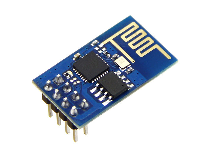
ESP-01
This is the first module that came out on the market. It is the cheapest and nearly the smallest module available. It is perfectly usable with the Arduino IDE for example.However, it comes with serious disadvantages. First, you can’t plug it into a breadboard without an adapter or you need to use jumper wires. Then, you don’t have access to all the input/output pins of the ESP8266 chip, which is a problem if you have complex projects that you want to build. However, for simple projects, this is a good module to start with.
Have a look at the pinouts:
ESP-01 Pinouts
1 | GND |
2 | GPIO1/U0TXD/SPI_CS1 |
3 | GPIO2/U1TXD |
4 | CHIP_EN/CH_PD |
5 | GPIO0/SPI_CS2 |
6 | RST |
7 | GPIO3/U0RXD |
8 | VCC(3.3V) |
ESP-WROOM-02 Module
ESP-WROOM-02 is a low-power 32-bit MCU Wi-Fi module, based on the ESP8266 chip. TCP/IP network stacks, 10-bit ADC, and HSPI/UART/PWM/I2C/I2S interfaces are all embedded in this module.It uses a 2 MB SPI flash connected to HSPI, working as the SDIO/SPI slave with the SPI speed of up to 8 Mbps. This module can be easily integrated into space-limited devices, due to its small size of only 18mm x 20mm x 3mm.

ESP-WROOM-02
This official WROOM board is perfect option if you are planning to build something using ESP8266 Core. This module has most of the things built in, you just needs few external components to get it working. The Board comes in SMD package, thus saving the space on the mother board. Due to its tiny size its perfect for IoT applications. Following pins are accessible on the WROOM board:
ESP-WROOM-02 Pinouts
Pin Number | Pin Name | Pin Functions |
|---|---|---|
1 | 3V3 | 3.3V power supply (VDD) |
2 | EN | Chip enable pin. Active high |
3 | IO14 | GPIO14; HSPI_CLK |
4 | IO12 | GPIO12; HSPI_MISO |
5 | IO13 | GPIO13; HSPI_MOSI; UART0_CTS |
6 | IO15 | GPIO15; MTDO; HSPICS; UART0_RTS |
7 | IO2 | GPIO2; UART1_TXD |
8 | IO0 | GPIO0 |
9 | GND | GND |
10 | IO4 | GPIO4 |
11 | RXD | UART0_RXD; GPIO3 |
12 | TXD | UART0_TXD; GPIO1 |
13 | GND | GND |
14 | IO5 | GPIO5 |
15 | RST | Reset the module |
16 | TOUT | It can be used to test the power-supply voltage of VDD3P3 (Pin3 and |
17 | IO16 | GPIO16; can be used to wake up the chipset from deep sleep mode. |
18 | GND | GND |
But it is very difficult to start using ESP-WROOM-02 PCB without any soldering, thus we are offering a presoldered ESP-WROOM-02 Adapter board in out store.Have a look at the adapter board below:
ESP-WROOM-02 with Adapter Baord
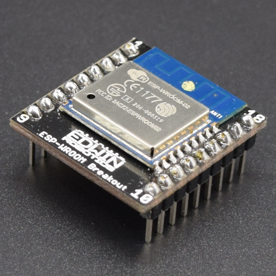
ESP-WROOM-02 Board with Adapter
This board is perfect to use with breadboard, you do not need any soldering, it will sit easily on the breadboard. This board will also give you the option to solder the board easily to proto boards, without any complication. The adapter board dimensions will be 25.5mm x 26mm.
We do have different types of ESP8266 boards from different manufacturers which uses ESP8266 as it core. The difference in these boards is that every manufacturer will add their own peripherals and their own standard pinouts, even some boards comes with onboard USB to Serial Converter, so it will be very easy to program those board. Have a look at the ESP8266 Boards we having with us.Below we had added the Summary table for ESP8266 modules, to get better idea and see the difference between them:
| Board ID | pins | pitch | form factor | LEDs | Antenna | Ant.Socket | Shielded | dimensions mm | Flash Size (KB & Mb) |
|---|---|---|---|---|---|---|---|---|---|
| ESP-01 | 8 | .1“ | 2×4 DIL | Yes | Etched-on PCB | No | No | 14.3 x 24.8 | 512KB – 4Mb |
| ESP-02 | 8 | .1” | 2×4 notch | No? | None | Yes | No | 14.2 x 14.2 | 512KB – 4Mb |
| ESP-03 | 14 | 2mm | 2×7 notch | No | Ceramic | No | No | 17.3 x 12.1 | 512KB – 4Mb |
| ESP-04 | 14 | 2mm | 2×4 notch | No | None | No | No | 14.7 x 12.1 | 512KB – 4Mb |
| ESP-05 | 5 | .1“ | 1×5 SIL | No | None | Yes | No | 14.2 x 14.2 | 512KB – 4Mb |
| ESP-06 | 12+GND | misc | 4×3 dice | No | None | No | Yes | 16.3 x 13.1 | 512KB – 4Mb |
| ESP-07 | 16 | 2mm | 2×8 pinhole | Yes | Ceramic | Yes | Yes | 21.2 x 16.0 | 1024KB – 8Mb |
| ESP-07S | 16 | 2mm | 2×8 pinhole | No | None | Yes | Yes | 17.0 x 16.0 | 1024KB – 8Mb |
| ESP-08 | 14 | 2mm | 2×7 notch | No | None | No | Yes | 17.0 x 16.0 | |
| ESP-08 New | 16 | 2mm | 2×8 notch | No | None | No | Yes | 18.0 x 16.0 | |
| ESP-09 | 12+GND | misc | 4×3 dice | No | None | No | No | 10.0 x 10.0 | |
| ESP-10 | 5 | 2mm | 1×5 notch | No | None | No | No | 14.2 x 10.0 | 512KB – 4Mb |
| ESP-11 | 8 | 1.27mm | 1×8 pinhole | No | Ceramic | No | No | 17.3 x 12.1 | 512KB – 4Mb |
| ESP-12 | 16 | 2mm | 2×8 notch | Yes | Etched-on PCB | No | Yes | 24.0 x 16.0 | 4096KB – 16Mb |
| ESP-12-F | 22 | 2mm | 2×8 notch | Yes | Etched-on PCB | No | Yes | 24.0 x 16.0 | 4096KB – 16Mb |
| ESP-12-E | 22 | 2mm | 2×8 notch | Yes | Etched-on PCB | No | Yes | 24.0 x 16.0 | 4096KB – 16Mb |
| ESP-12S | 16 | 2mm | 2×8 notch | Yes | Etched-on PCB | No | Yes | 24.0 x 16.0 | 4096KB – 16Mb |
| ESP-13 | 18 | 1.5mm | 2×9 | Etched-on PCB | No | Yes | 20.0 x 19.9 | 4096KB – 16Mb | |
| ESP-14 | 22 | 2mm | 2×8 + 6 | 1 | Etched-on PCB | No | Yes | 24.3 x 16.2 | |
| WROOM-02 | 18 | 1.5mm | 2×9 | No | Etched on PCB | No | Yes | 20.0 x 18.0 | |
| WT8266-S1 | 18 | 1.5mm | 3×6 | 1 | Etched on PCB | No | Yes | 15.0 x 18.6 |
Hope things are more clear to you now, before we finish with this blog, have a look at variety of projects and tutorials based on the ESP8266 boards we had added in our blog.
0 Comments
Trackbacks/Pingbacks