Halloween Umbrella using EL Wire
Are you looking for an addon to your Halloween costume or want to make one on your own with items available with you? Try building an umbrella with EL wire. We are going to show you how to make one attractive umbrella, which will glow and change its glow pattern just by tilting or shaking the umbrella. Those who are unaware of EL Wire, we want to describe it in a single sentence that, Electroluminescent wire (often abbreviated as EL wire) is a thin copper wire coated in a phosphor which glows when an alternating current is applied to it.
Parts Needed:
- EL Wire Starter Kit
- EL Invertor Battery Pack (Optional)
- Enclosed Battery Holder (optional)
- Tilt Switch (Optional)
We had used all the above parts mentioned for this project. The EL Wire Starter Kit includes Invertor battery pack already, thus there is no need to buy this separately, if you have EL wire starter kit with you. We used the Enclosed Battery Holder rather than using EL Wire Battery Pack casing because this holder comes with an ON/OFF Switch to disconnect the power supply from the circuit to stop battery from draining out. We had used tilt switch to add effects to the EL Wire.
Assembly Steps:
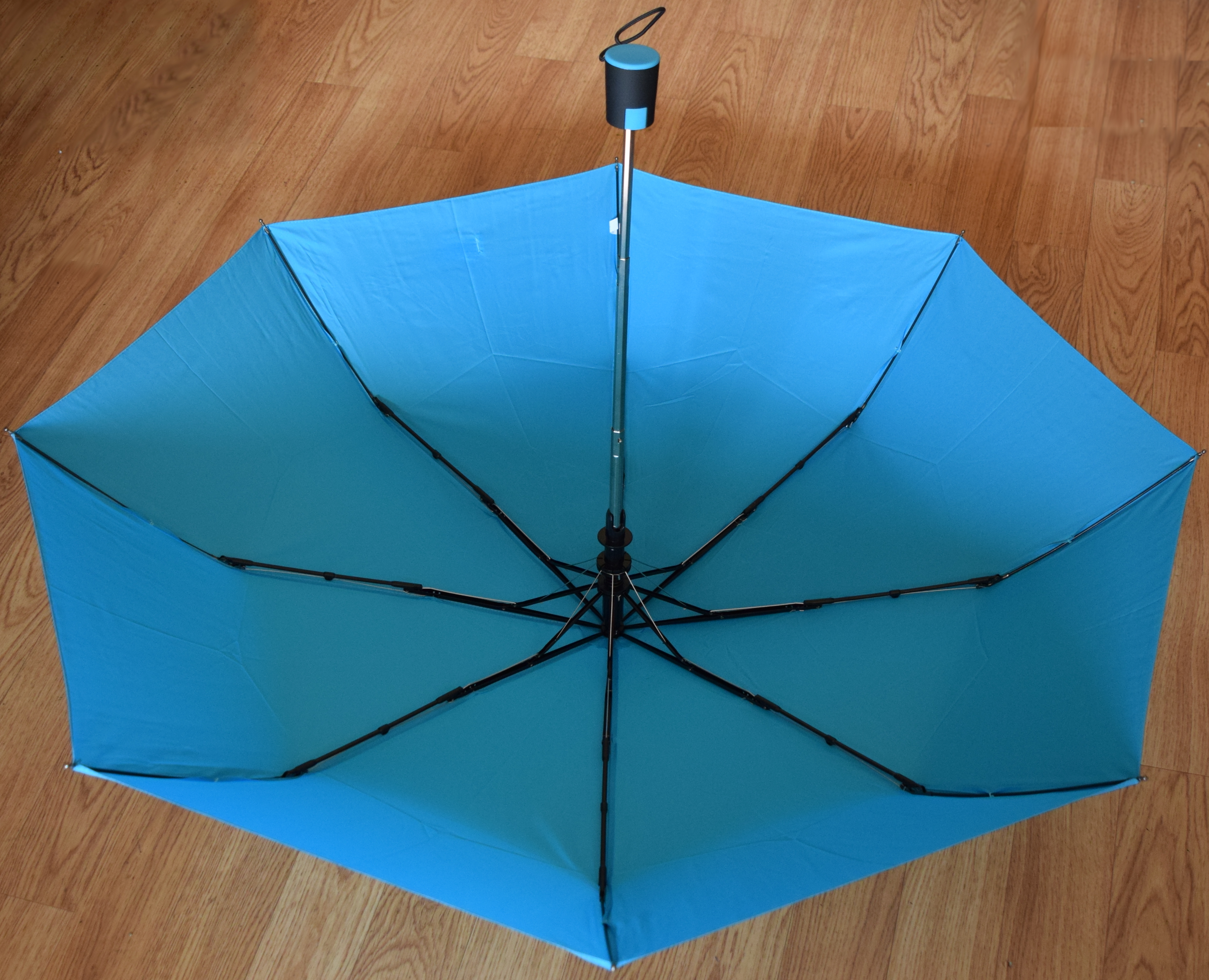
- First you need to do is to find an umbrella as per your need. You are free to select any kind of umbrella as per you choice. We had bought one shiny and attractive umbrella for our purpose

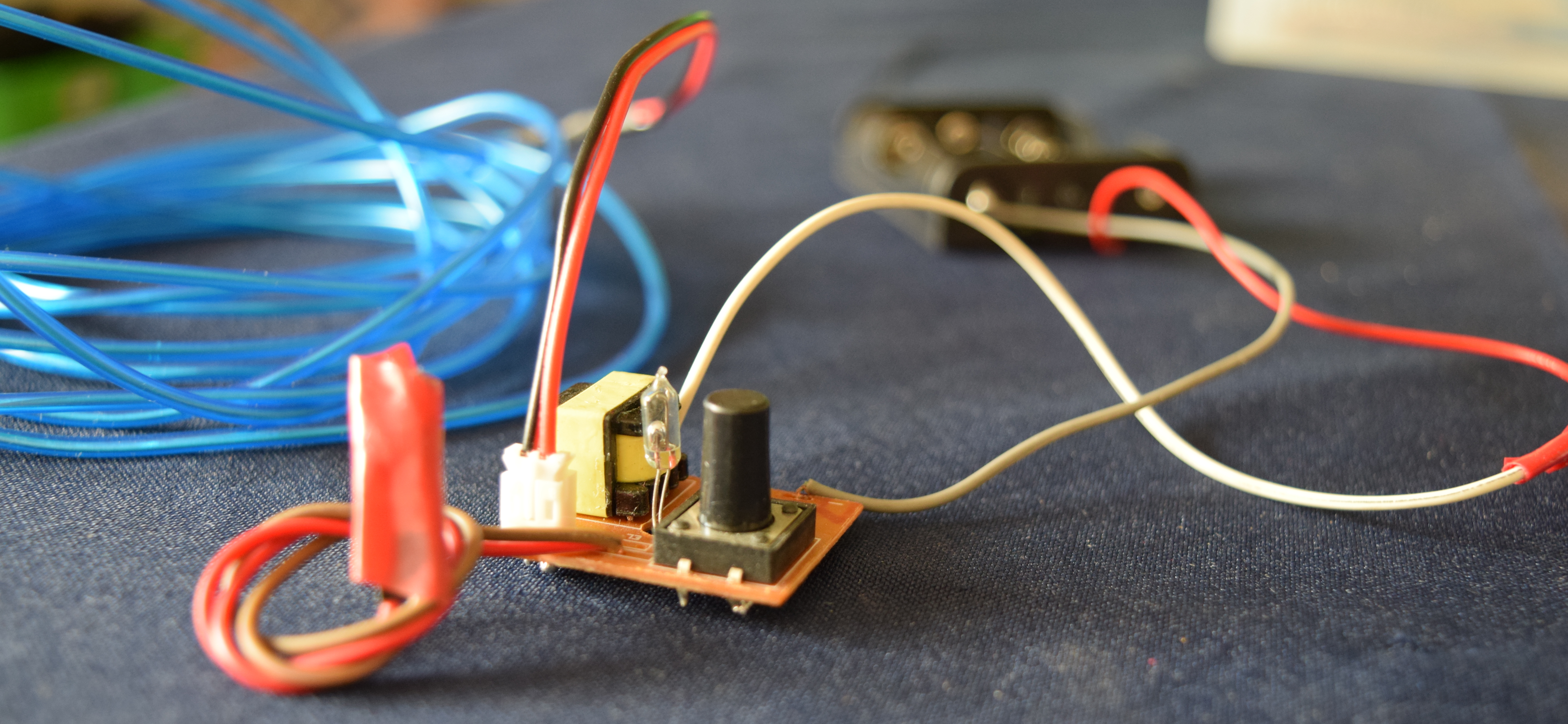
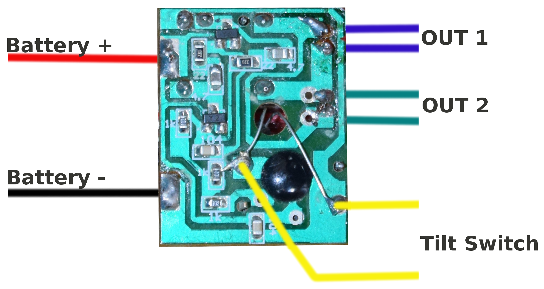
2. Now, its time to do some hacking. The EL wire is powered from Invertor pack provided with the kit, the invertor pack is capable enough to produce high AC voltage from two 1.5v AA Batteries to make EL Wire0 glow. All you need to do is to unscrew ans open the Invertor battery pack and you will see one small PCB as shown below:
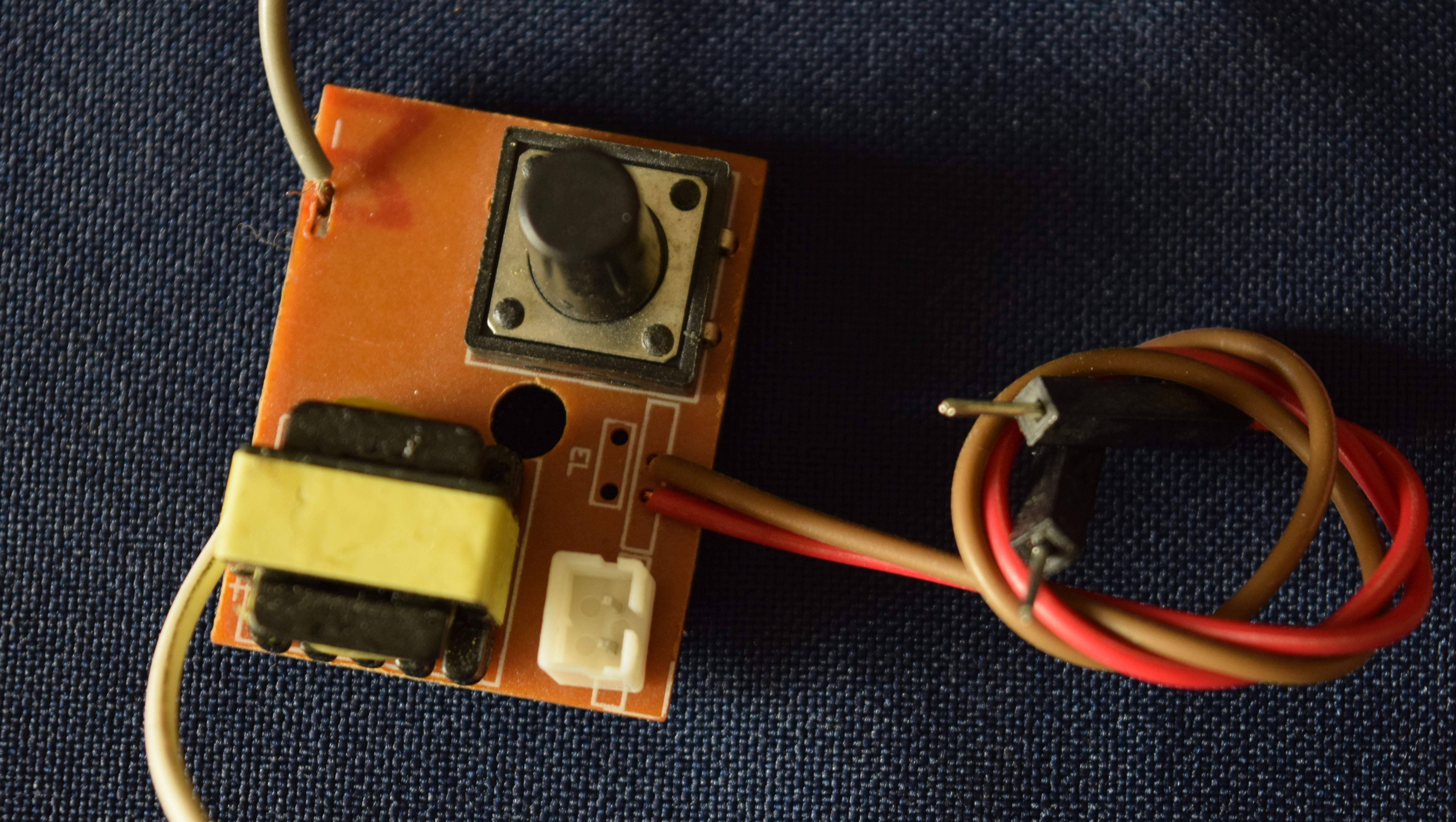
Ignore the jumper wires shown in the above image, your PCB have one connector in the same slot. You will find the + and – sign on the PCB, this is where the battery is connected, remove the battery compartment and the connector from the PCB and solder wires in the slot and connect it to Enclosed Battery Holder as shown below:
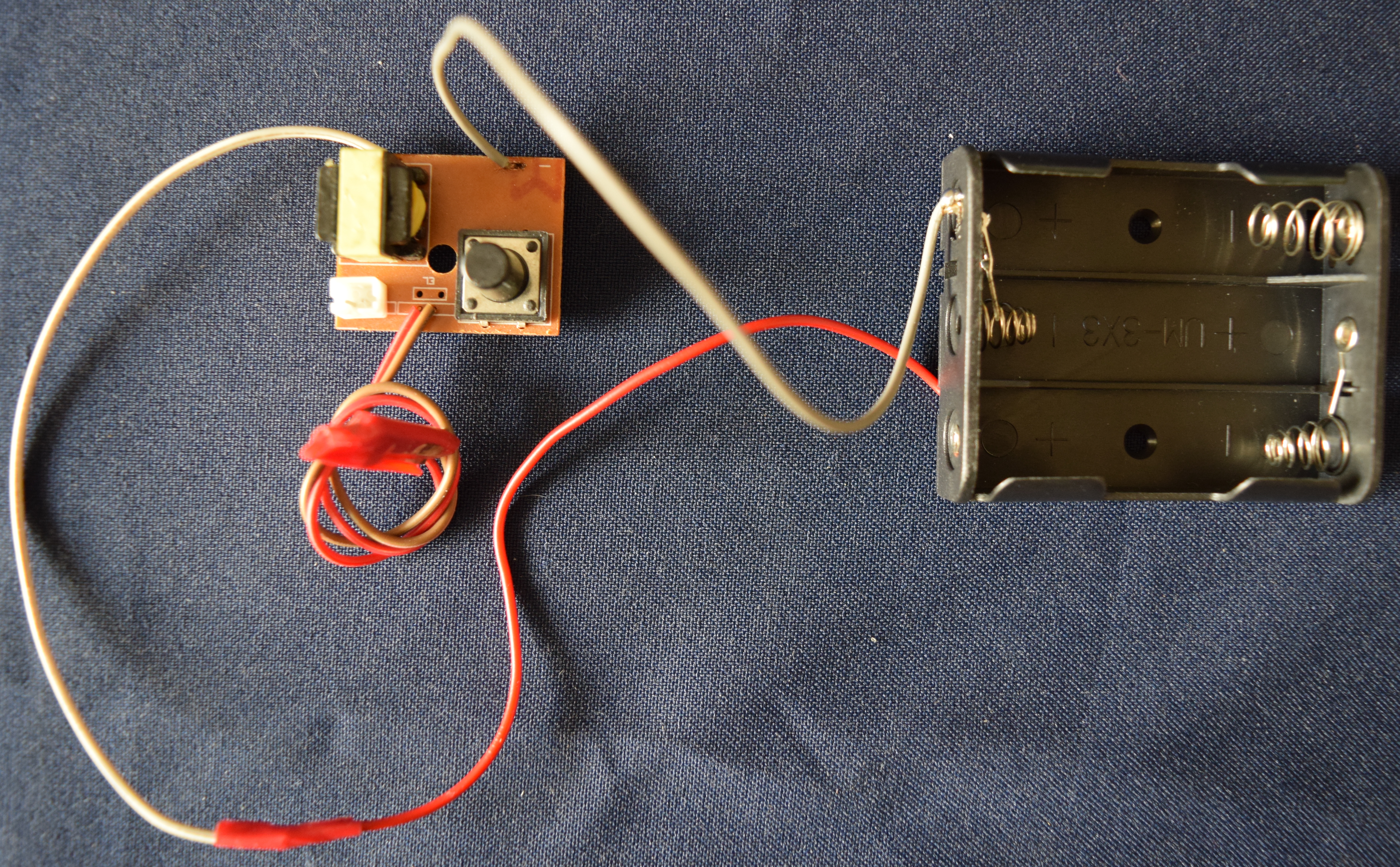
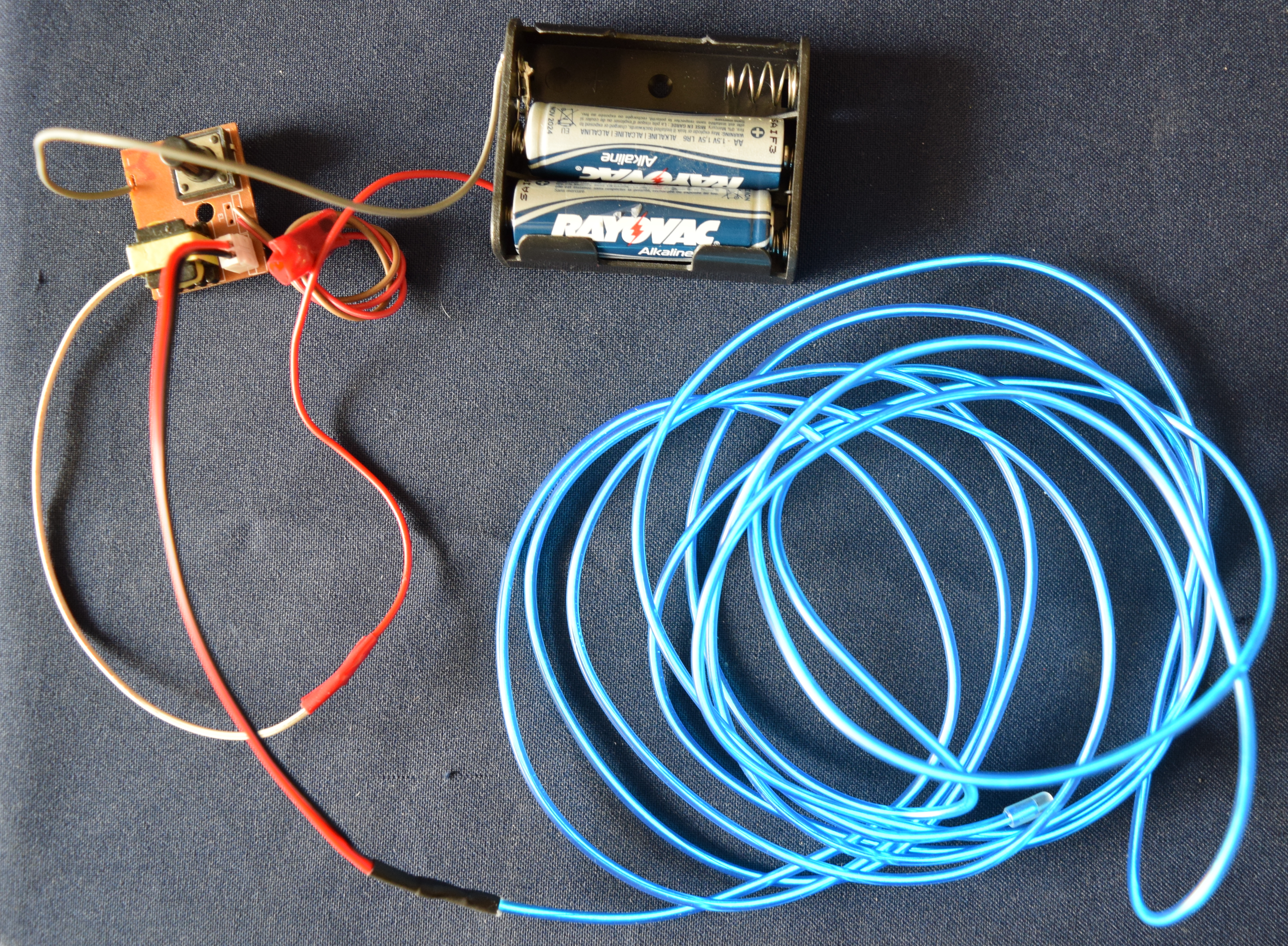
3. Before going further, make sure your circuit is working till this point, connect your battery in the compartment, we had used three cell compartment and modified its connection to use two cell only. Plug in your battery and EL Wire as shown below:
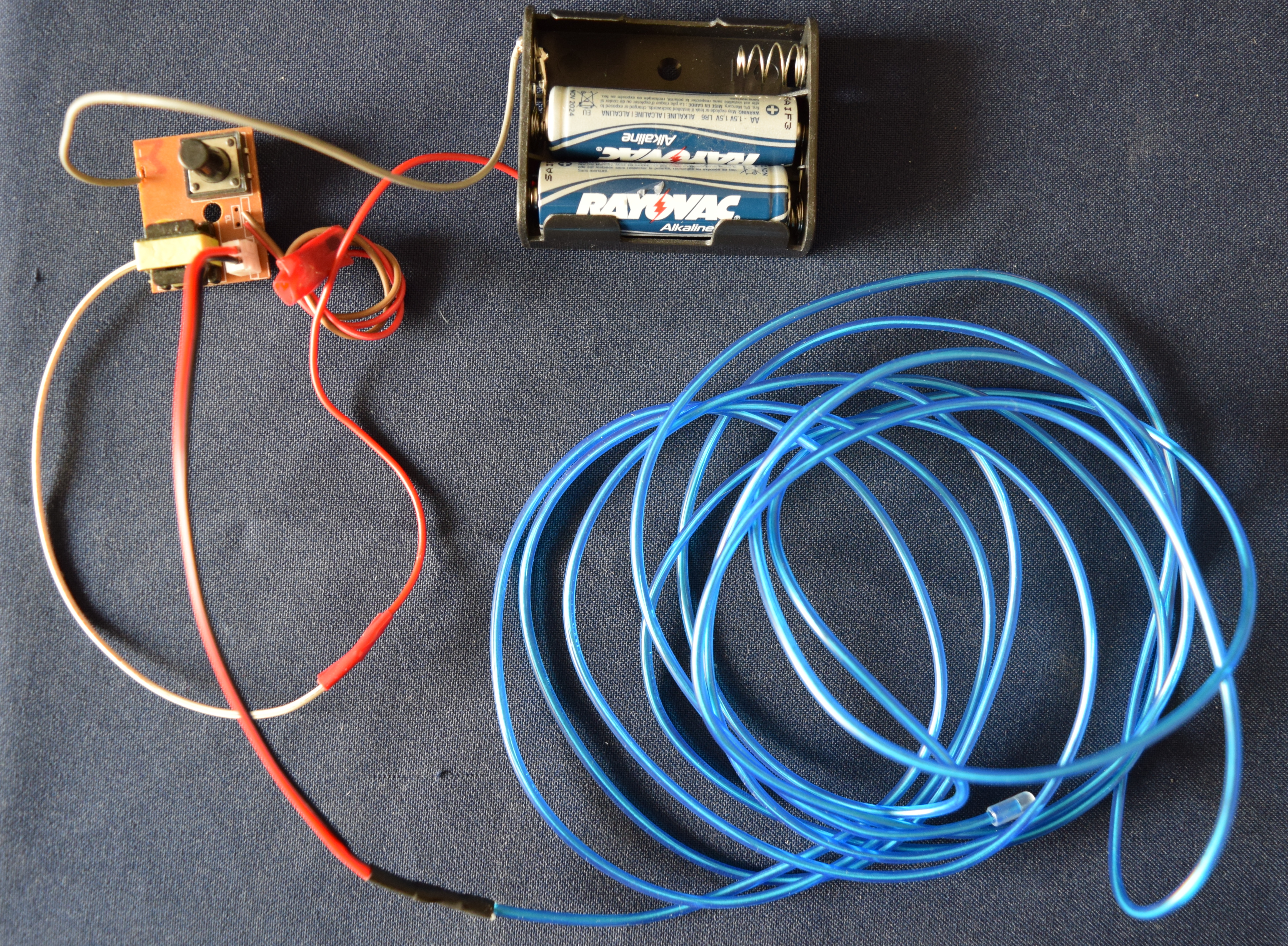
4. Now, test your circuit by pressing the switch, to check whether your circuit is working or not. The PCB Supports four modes of operation: ON/OFF, Constant Glow, Blink and Fast Blink. For first key press, your EL-Wire must glow Constant as shown below:
5. Its time to automate the switch, since we don’t want to press the key always to turn on/off/blink the EL Wire. We will add the Tilt Switch for this purpose. you have to solder the tilt switch in parallel to the switch, this will make sure that both the switches remain functional in the PCB. If You are still confused with what we are talking about, no need to worry, just look at the PCB and you will notice that two legs of the switch is connected to PCB track and and two are left alone, so you have to solder the tilt switch to the two legs which is connected to the PCB track.
Refer the image below, for the setup we made, we used the screw mount hole in the PCB to pass tilt switch through it and we had soldered the tilt switch legs to the tactile switch. Since the legs of Tilt switch is flexible, you are free to change its orientation as per your need.
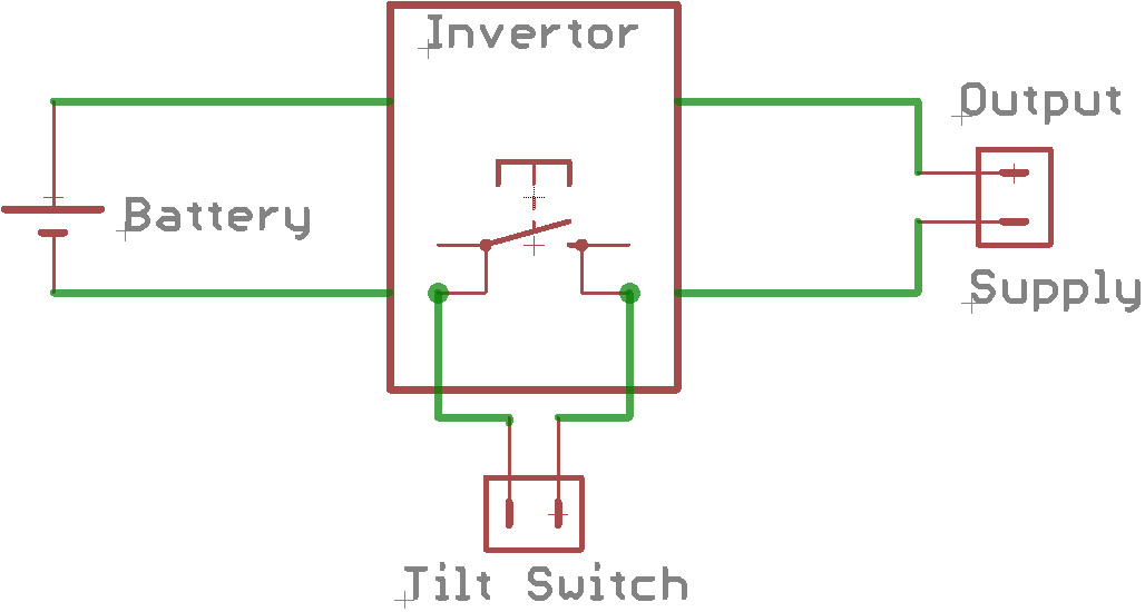
The tilt switch comes with a ball inside a capsule, which will make contacts with the terminal on normal position and disconnects when tilted. Refer the Schematics and Connections shown below for the whole setup:
6. Its time to mount all this to the umbrella, we had stitched the EL Wire as shown, you can opt for any kind of pattern you need. Make sure to check your pattern for the length of EL Wire available with you, before starting the stitching.

We brought down the EL Wire connector and provided enough length to connect with the PCB.

Close the battery pack, so that it won’t come out and attach it to the Umbrella.


We used tape to attach the battery holder and PCB to the umbrella, as shown above. Once done, turn on the power supply and check whether your umbrella is glowing or not after pressing the tactile switch.
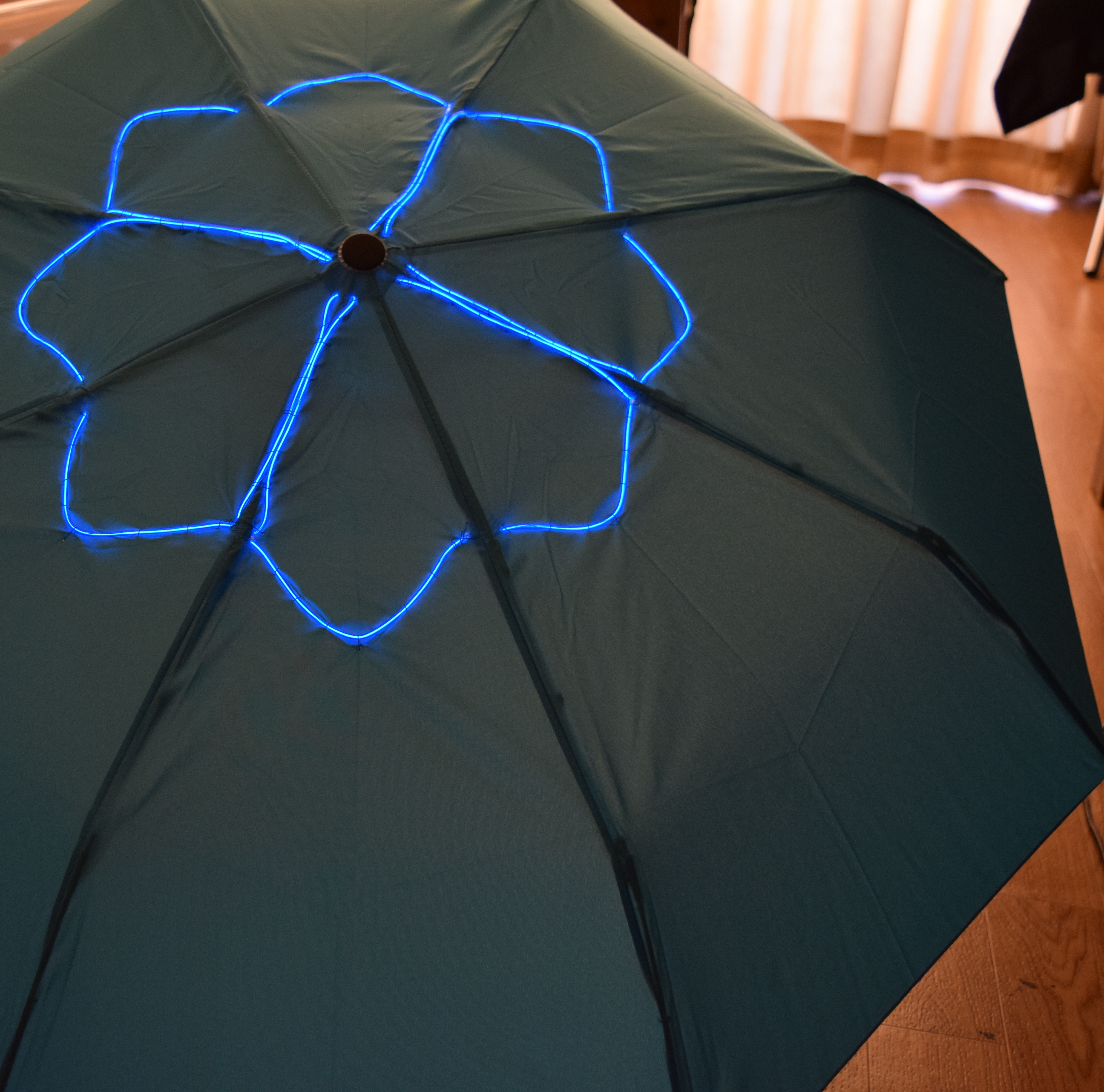
If all went fine, you will get glowing umbrella as shown below:
The effects shown above will be visible either by pressing the switch or just tilting the umbrella, make sure to adjust your tilt switch, after you mount the PCB to the umbrella, try the setup on your umbrella or any other item available with you. We will be happy to hear from you, let us know about your creation in the comment section.