eSocket
Now a days we have seen lots of devices are available in the market which can be controlled over the internet either using web browser or using mobile application. This project is all about controlling the Power socket over internet using web browser. We had used ESP8266 Thing in this Project, since it will give you the flexibility to make a flexible product with internet connectivity using the wifi. Particle photon is another option to be used in this project and it will give great advantage over ESP8266 Thing that, you can flash the code over the internet without bothering about where the product is. Now we will show you how to build your own eSocket.
Parts Needed
- ESP8266 Thing
- FTDI Basic USB to Serial Converter
- Relay
- ULN2803
- Power Supply 5v
- Power Supply 12v
ESP8266 Thing
The ESP8266 is a low-cost Wi-Fi chip with full TCP/IP stack and Microcontroller capability produced by Shanghai-based Chinese manufacturer, Espressif. There are many third party modules With ESP8266 available in the market and you can decide which one suits best for your application, we are using the Sprakfun ESP8266 Thing in this tutorial.
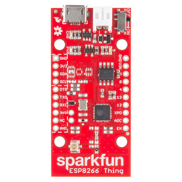
The SparkFun ESP8266 Thing is a breakout and development board for the ESP8266 WiFi SoC – a leading platform for Internet of Things (IoT) or WiFi-related projects. These are some features of the board:
ESP8266 Thing Features:
- All module pins broken out
- On-board LiPo charger/power supply
- 802.11 b/g/n
- Wi-Fi Direct (P2P), soft-AP
- Integrated TCP/IP protocol stack
- Integrated TR switch, balun, LNA, power amplifier and matching network
- Integrated PLLs, regulators, DCXO and power management units
- Integrated low power 32-bit CPU could be used as application processor
- +19.5dBm output power in 802.11b mode
- Arduino IDE integration
- Breadboard Compatible Breakout Headers position
- Power On-Off Switch
- Status LED
- Operating Voltage: 3.3v
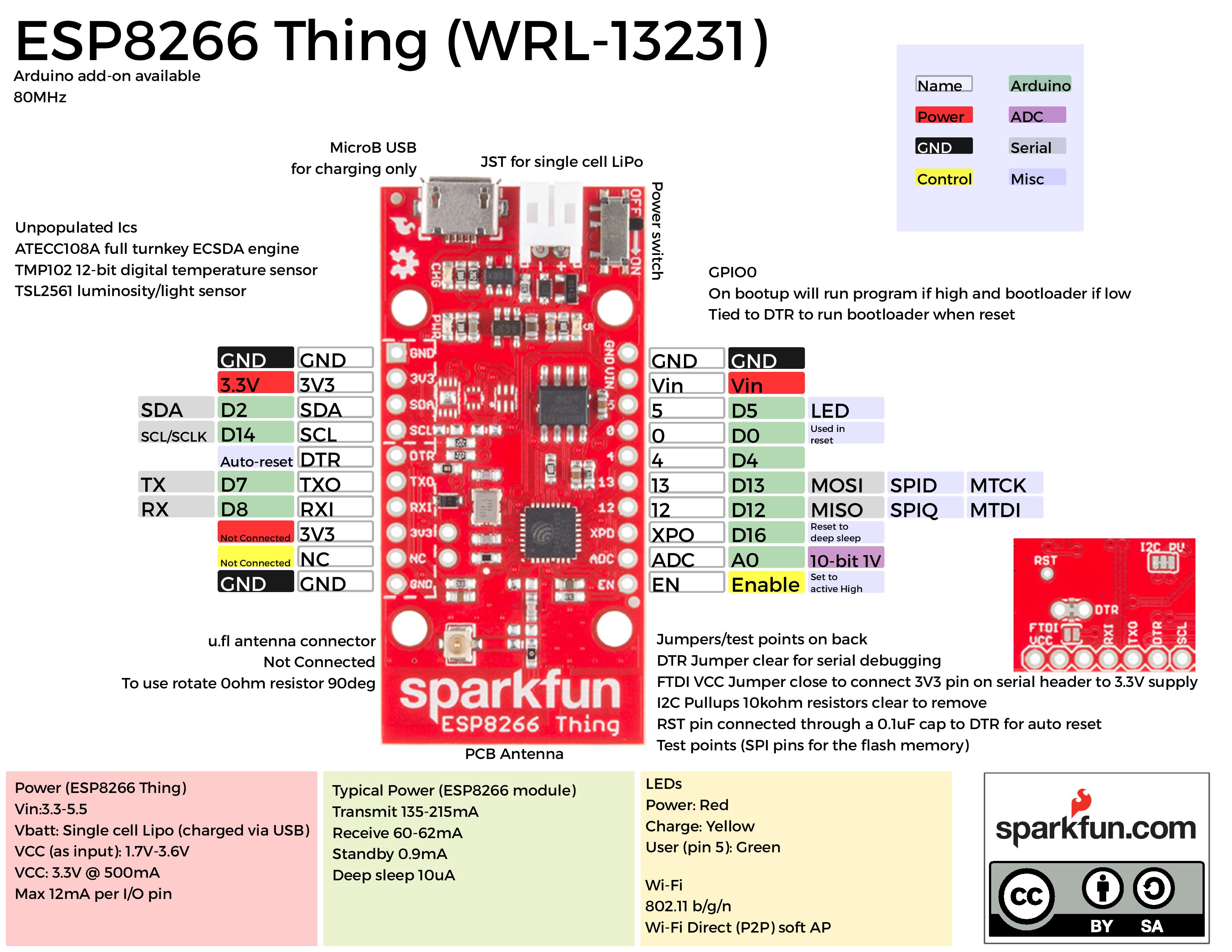
Refer the Graphical Datasheet for hardware description
Programming the Thing:
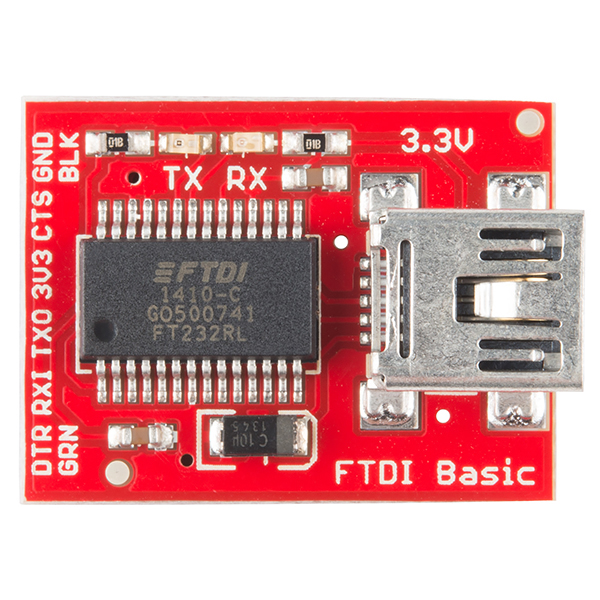
The ESP8266 has a built-in serial bootloader, which allows for easy programming and re-programming. You don’t need a specialized, expensive programmer – just a simple, USB-to-Serial converter.
We use a 3.3V FTDI Basic to program the Thing, but other serial converters with 3.3V I/O levels should work. The converter does need a DTR line in addition to the RX and TX pins.The FTDI Basic’s 6-pin header matches up exactly to the Thing’s 6-pin serial port header. To set up for programming, simply connect the FTDI directly to this port – take care to match up the DTR and GND pins!
Note: While programming the Thing, it’s best to power it off USB. We’ve noticed programming is more likely to fail if the Thing is only powered via the battery.
Going further we need to interface relay with ESP8266 Thing, since we need to control the power socket, the relay we used in this project is of Industrial grade 10A, 250vAC rated and Coil Supply with 12v DC control voltage, you can use any other relay as per your convenience. Our ESP8266 Thing runs on 3.3v control logic, thus we are not able to straight away control the relay from ESP8266 IO Pins, we used ULN2803 Darlington array IC as relay driver, this IC is easily available in the market and can be used to control 8 relays at a time, since we need to interface just one relay to control the socket, we used only one channel of the IC.
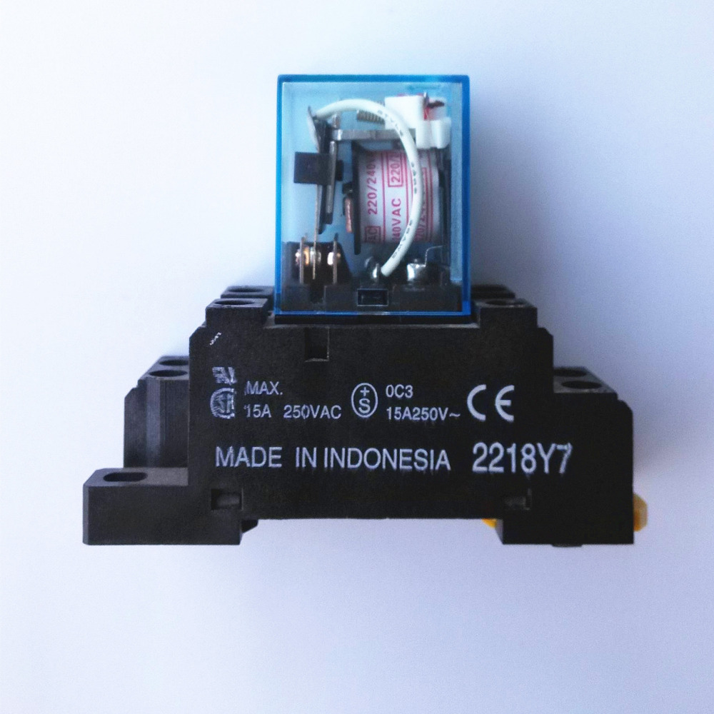
Relay
Specifications:
- DPDT
- Mini Middle Electromagnetic Relay
- 8Pins 2NO+2NC
- Current:10A
- contacts:silver plated gold
- LED color:green
- Terminal form:socket type
- LED voltage: AC220/240V
- 12V DC voltage Controlled
- Secondary Side: 10A/240vAC, 10A/28vDC
The relay base module is separate part and needs to be purchased separately, its is rated for 15A, 250v AC, all the pin marking are made on the base itself thus connection is really simple, just refer the schematic shown on the relay body itself.
ULN2803
The ULN2803A device is a high-voltage, high-curren Darlington transistor array. The device consists of eight NPN Darlington pairs that feature high-voltage outputs with common-cathode clamp diodes for switching inductive loads. The collector-current rating of each Darlington pair is 500 mA. The Darlington pairs may be connected in parallel for higher current Types of Logic capability.
Features:
- 500-mA-Rated Collector Current (Single Output).
- High-Voltage Outputs: 50 V
- Output Clamp Diodes
- Inputs Compatible with Various types of Logic
- Relay-Driver Applications
- Compatible with ULN2800A Series
Simplified Schematics:
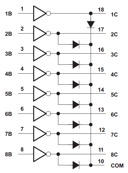
Pin Diagram:
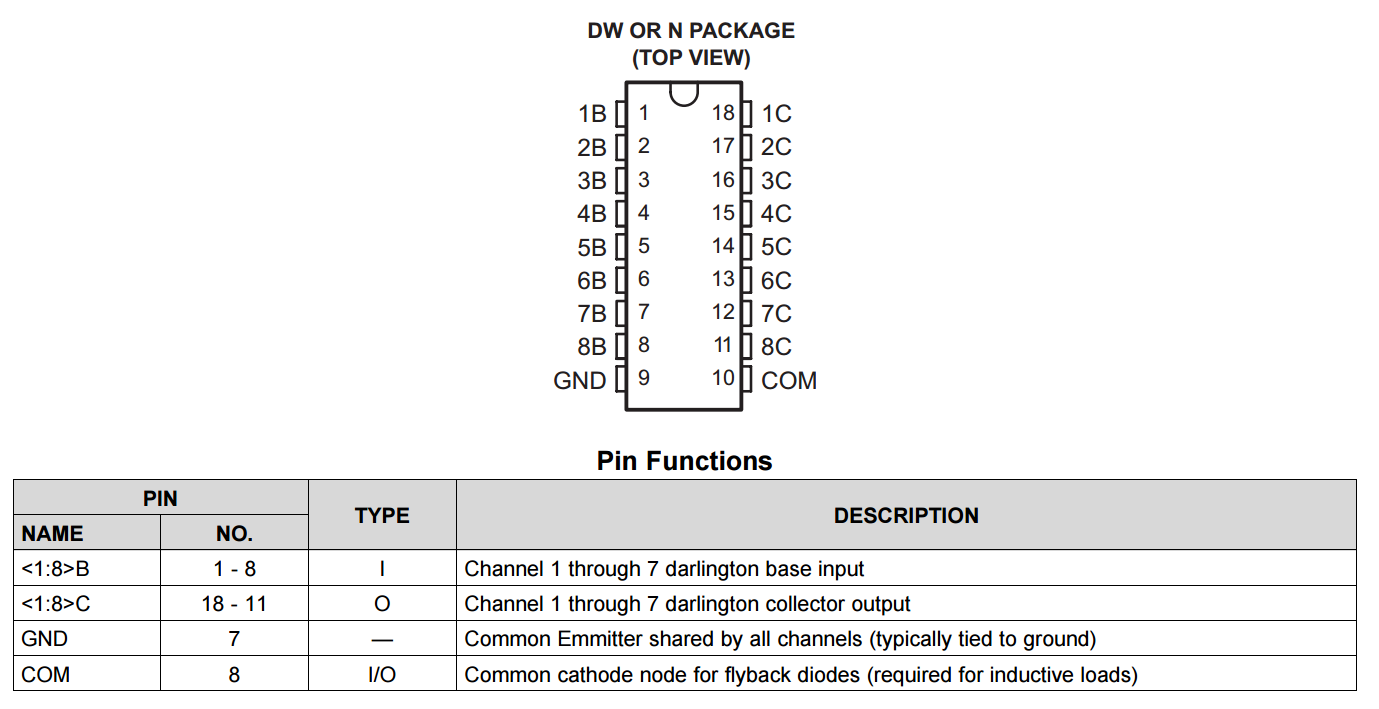
Connections with ULN2803 are really simple, the channel mentioned with 1B , 2B, …, 8B all are inputs and you can pass on your logic control voltage from microcontroller to these pins, its 3.3v/5v Compatible. The corresponding inverted out will be present on the other side i.e 1C,2C,…,8C.
Connect the GND pin with GND from power supply and COM pin with 12v Supply Input, When a logic one is fed to 1B , you are able to get the ground from 1C, we used the channel 8, thus we connected 8B with ESP8266 pin 12 and and 8C to relay coil ground Pin, we already provided relay coil +ve pin with 12v supply. Refer the schematics in the next section to get a clear idea of the circuit connection.
Click here to See the Datasheet.
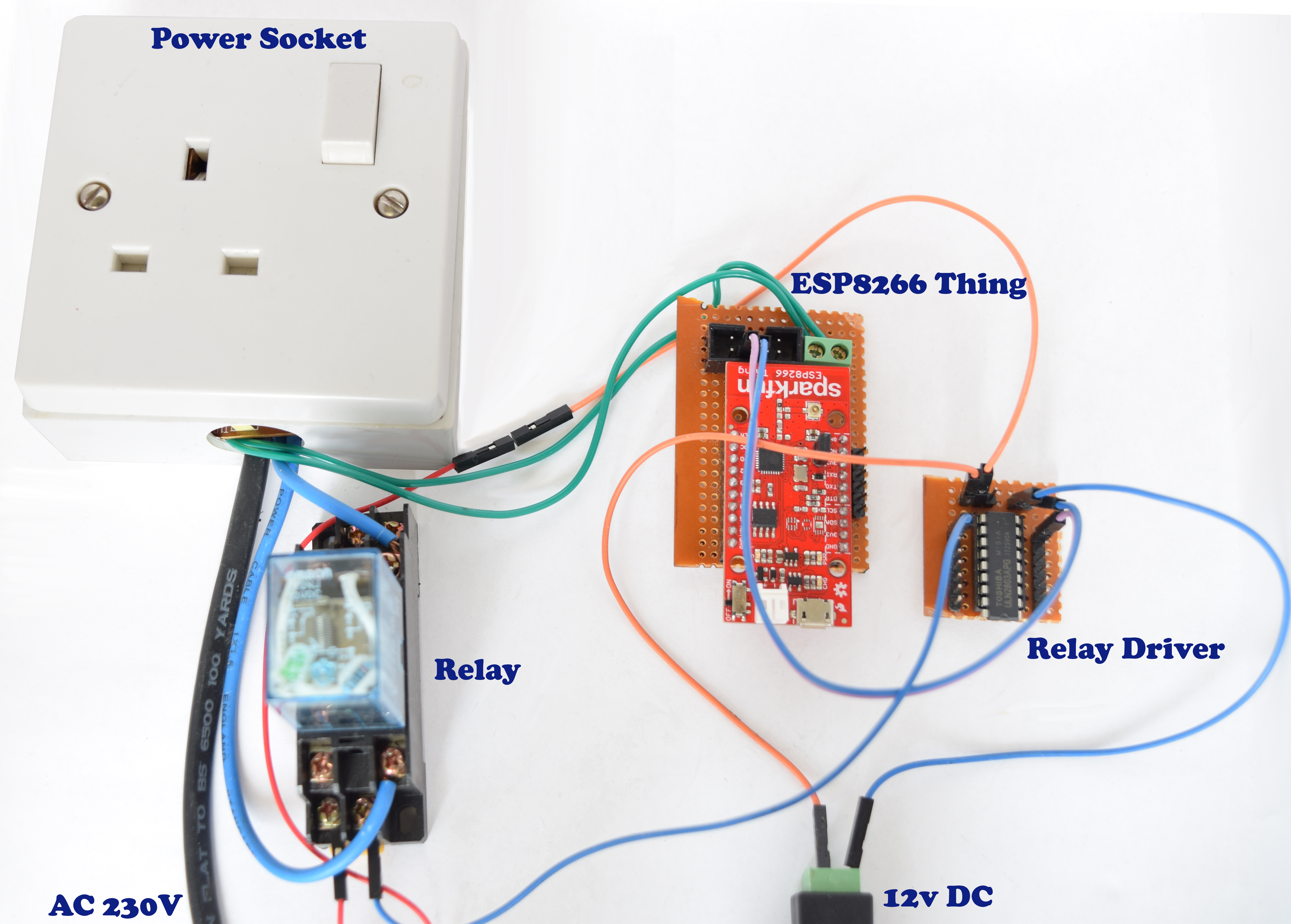
Circuit Integration
The complete circuit integration won’t take much time, you can use breadboard to integrate the circuit to save your time, we used the protoboards to make breakout boards for the ULN2803 IC and ESP8266 Thing. we used fritzing to make breadboard design for you, just refer the circuit diagram to build your own circuit.
The 12v and 5v power supply is something you can get from adapter around you, power socket or power extension box is something you need to buy. you must buy a big box to fit in maximum circuit Inside it, Precaution must be taken when you assemble this high power circuits.
Schematics:
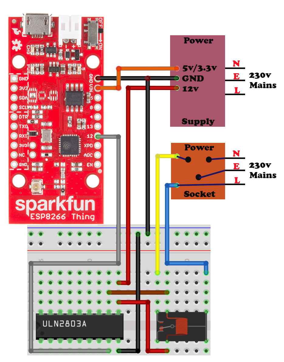
If you check the above image, you won’t find 5v power supply, its because we fitted it in inside the power socket, the two green wires coming out of the power socket is 5v and GND. The rest you are able to figure out just by referring the schematic shown. We had added working video of the prototype to show you how the things work, use the source code we provided to build your own device.
Source Code
//ON Device Control command: http://192.168.1.167/led?params=1
//OFF Device Control command: http://192.168.1.167/led?params=2#include <ESP8266WiFi.h>
#include <aREST.h>#define PIN1 13
#define PIN2 12aREST rest = aREST();
// WiFi parameters
const char* ssid = “xxxx”;
const char* password = “xxxxxxxx”;// The port to listen for incoming TCP connections
#define LISTEN_PORT 80// Create an instance of the server
WiFiServer server(LISTEN_PORT);// Declare functions to be exposed to the API
int ledControl(String command);
void setup(void){
Serial.begin(57600);
pinMode(PIN1,OUTPUT);
pinMode(PIN2,OUTPUT);// Function to be exposed
rest.function(“led”,ledControl);// Give name and ID to device
rest.set_id(“1”);
rest.set_name(“esp8266”);// Connect to WiFi
WiFi.begin(ssid, password);
while (WiFi.status() != WL_CONNECTED) {
delay(500);
}// Start the server
server.begin();
Serial.println(WiFi.localIP());
}
void loop() {
// Handle REST calls
WiFiClient client = server.available();
if (!client) {
return;
}while(!client.available()){
delay(1);
}
rest.handle(client);
}
int ledControl(String command) {
int state = command.toInt();if(state==1){
digitalWrite( PIN1, 1);
digitalWrite( PIN2, 1);
}else
if(state==2){
digitalWrite( PIN1, 0);
digitalWrite( PIN2, 0);
}return 1;
}
Make sure that you had replaced the Wifi SSID and password credentials in the code with your own network one.
Once you upload the code to you device, you are able to get your local IP address from the serial terminal, open the arduino serial terminal at 57600 baud rate, when you are able to see the IP address just copy it and open your browser either from computer or mobile, whichever connected to same network, use the following two commands in the address bar to control the socket:
//ON Device Control command: http://192.168.1.167/led?params=1
//OFF Device Control command: http://192.168.1.167/led?params=2
Replace the IP address with you own IP address in the command shown above. Whenever a successful communication is established between ESP8266 and Web, you will get response from the ESP8266 at web end, you are able to see this in the video we added.
We had used the arest in this project, which made our task looks simple, using the arest command line we are able to pass on multiple parameters(all at once) to ESP8266 as string or vise versa.
Download the arest library to run the above code. you need to unzip and copy the library to the arduino library folder.
If you are a web developer the things will be more easier for you, just use the mentioned commands in your web page to link it to the web User Interface. In the next part we will come with more advanced options for the same project so that things will be more easier for you.