230v/110v AC Mains Detection Module Hookup Guide
Want to check if you left your lights ON remotely, need to detect the zero crossing point for your dimming circuit or do you just need to interface a 230V signal to your Arduino? The AC Mains Detector board simplifies interfacing high voltage signals by giving a digital output when an AC voltage is detected. By disabling the on board capacitor, zero crossing detection is possible as well.
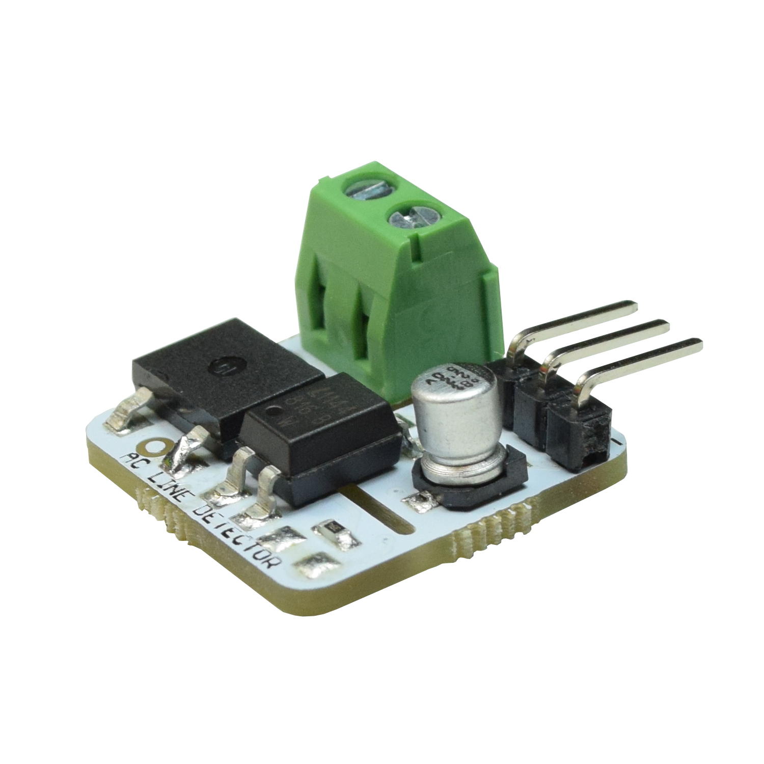
AC Line detection Module
You can buy this item from the following links:
Within GCC: Edwin Robotics
International Order: Tindie

Let us have a look at the guide contents, refer to the list below:
-
Components
-
Board Pinouts
-
Circuit Schematics
-
Interfacing with Arduino
-
Zero Crossing detection using Arduino
Components
 AC Line detection Module | 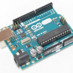 Arduino UNO | 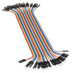 Male-Female Jumper wires |
Board Pinouts
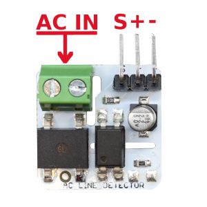 Top Side | 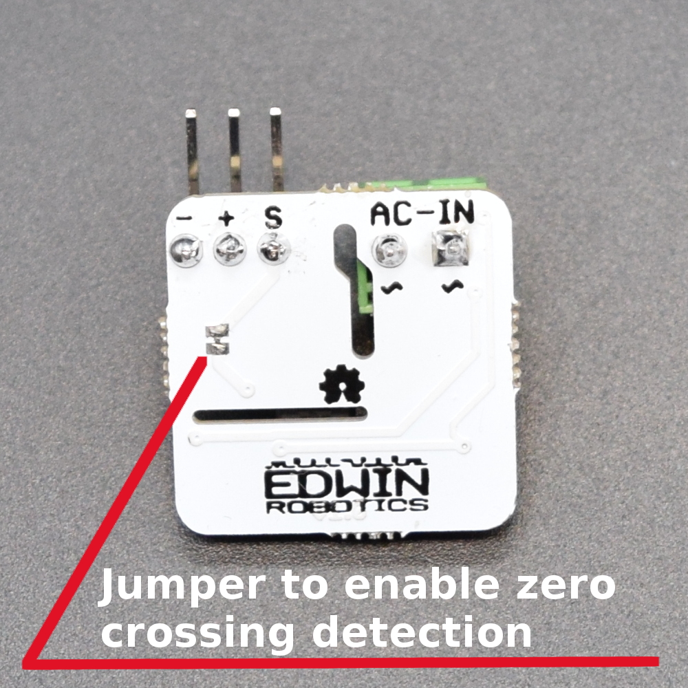 Bottom Side |
- AC-IN – Connect the AC line that needs to be detected here.
- – (negative sign) – Connect to ground of microcontroller
- + (positive sign) – Connect to VCC of microcontroller in case external pull-up is required
- S – Connect to a digital/interrupt pin of microcontroller
Note: Working with AC voltages is DANGEROUS, care must be taken to prevent any short circuits or mistakes in connection. And as always, you are doing this project at your own risk and Edwin Robotics or the Author cannot be held liable for any damages.
Circuit Schematics
The circuit consists of two main parts, first is the Bridge Rectifier (DB107) which converts the AC signal to DC and the second is the Optocoupler (LTV816), which provides isolation between High voltage(HV) side and Low Voltage (LV) Side.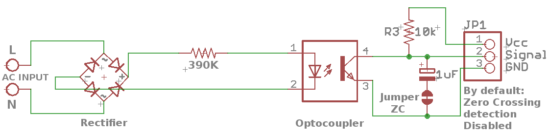
A pull-up resistor is provided for use with microcontrollers (e.g. ESP8266) that do not have an internal pullup resistor.
Interfacing with Arduino
The hardware connections are pretty straightforward. On the low voltage side the + (positive symbol) goes to VCC of microcontroller, – (negative symbol) goes to GND and S goes any digital/interrupt pin. On the high voltage side, the AC lines are connected.
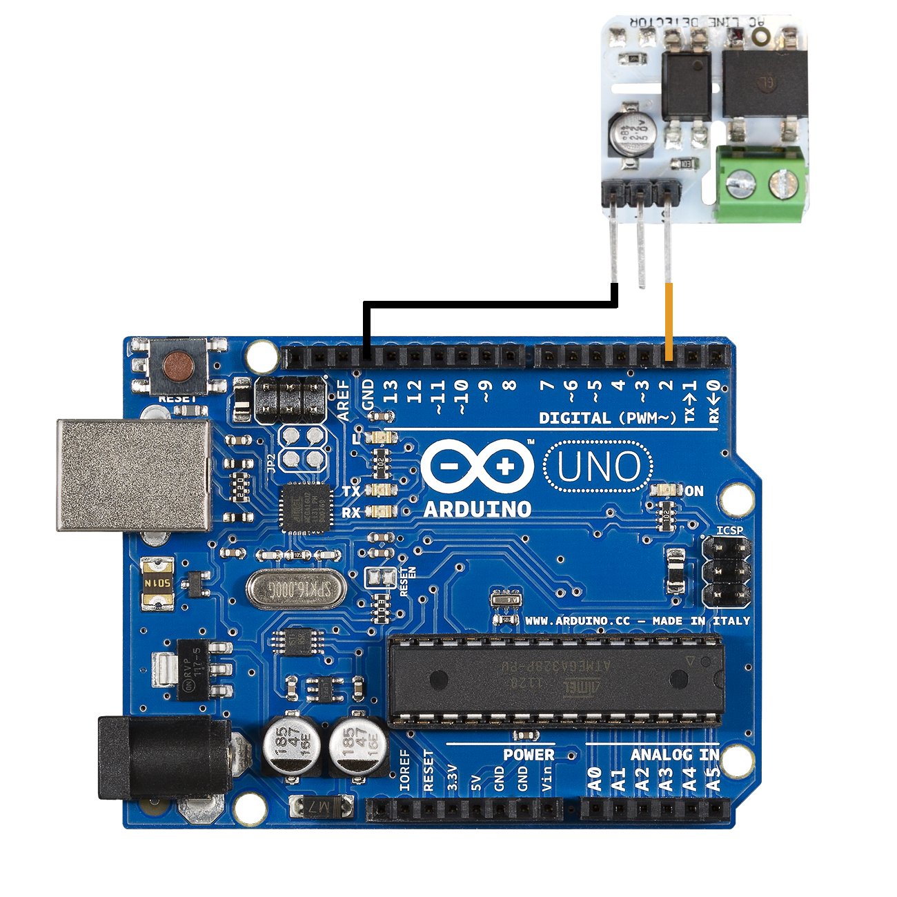
Arduino Connections
In this example, Pin 2 on the arduino is used in this example as it can be used as an interrupt pin as well.
Sample Code:
#define Signal_Pin 2  // Modify this pin as per your connection

void setup() {
  pinMode(Signal_Pin , INPUT_PULLUP);
  Serial.begin(9600);
}

void loop() {
  if ( digitalRead(Signal_Pin) == 0 )
    Serial.println (" AC Mains 230v Detected ");
}
Note: Do not touch the PCB once powered, you can get electrocuted. Keep it away from reach of humans/Animals. Make sure that there are no shorted wires, when connecting the 230v AC mains supply.
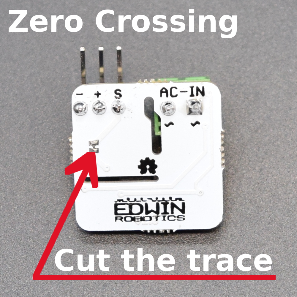
Zero Crossing Detection using Arduino
By default zero crossing detection is disabled by the use of a 2.2uF capacitor, in order to use the board for zero crossing detection the capacitor needs to be bypassed by cutting the trace shown below. It can be resoldered at any time later to disable zero crossing:
Modify the jumper
The Arduino connection will be same as before, upload the following code and view the output on Serial Monitor at 9600 baud rate:
#define Signal_Pin 2 //Use Arduino Pin 2 or pin 3, both supports hardware interrupt
int counter=0;

void setup()
{
  pinMode(Signal_Pin , INPUT_PULLUP);
  Serial.begin(9600);
  attachInterrupt(0, zero_crosss_int, RISING);  // Choose the zero cross interrupt # from the table above
}

void zero_crosss_int()  // function to be fired at the zero crossing to dim the light
{
  counter++;
}

void loop()
{
  Serial.println(counter);
}
You can see that the counter value increases with every cycle of AC line and the moment you turn off the AC line, the counter Stops as well.
I tried making this circuit…….but after 470kohm resistor, output is just 1v…….so it’s not working…. weather any change in resistance values?
Hi Ajith,
Let us know the following things:
1. Whether you used the same rectifier as mentioned in the schematic or some other ?
2. Whether you tried reading the signal pins with micro controller? If so, please let us know the details. If not try reading the signal pin with and without placing the capacitor in the circuit and share the details with us.
“weather any change in resistance values?” – you can try different values of resistance available with you, ranging: 47k ~ 1M
Thanks
Abhishek Nair
I believe there are two problematic point here:
1, Why that enormous 400V capacitor needed. It get only the LED forward voltage (2-4V maybe) . I think a small ceramic cap more than enough.
2, The forward current of the opto LED is setted by the 1Mohm res. It is than (case of 230V AC) 0.23mA. The CTR value of the opto is about 30-40%. So on the other side, the transistor collector current less than 0.1mA. On 10kohm, the voltage drop going to be less than 1V. I thing Arduino will not detect this voltage change on a digital input.
Hi Zoltan,
Whether you built this circuit and tried it out ?
1. The output from the rectifier is the range of 200v DC, i.e why we used a high voltage rated capacitor available with us. We used the polarized Electrolytic Capacitor here to let it store the charge, rather than bypassing it. If you have a look at the 4n35 Datasheet, you can see in the electrical characteristics that forward voltage for the built in led is 1.3~1.5v @ 10mA forward current which makes it ideal for this application.
2. The 10Kohm Resistor is used to pulled up the Signal Line, thus if there is no AC input the Signal line will stay at 5V itself and when we power up the AC line, the drop is there as mentioned by you and we are able to detect this change from the Arduino or any other microcontroller.
Can I replace the 4n35 for pc817 ? Where did you find out this 4n35 in SOP4 SMD ?
Hi there,
Yes you can replace the 4n35 with pc817, make sure to take care of the LED anode and cathode connections. We had used LTV-816 Optocoupler in the PCB which comes in SMD package, we had removed the text from the schematics to avoid confusion, hope this helps.
Is this module available for sale on any website?
Dear Balaji,
Yes you can order the item from this link: https://shop.edwinrobotics.com/sensors/960-ac-mains-zero-crossing-detection-module.html
Hello,
from the page title it seems that the circuit can detect both 110 VAC and 220 VAC; can you confirm that the LTV 816 can handle both voltages without changing the circuit? Also I need to detect 12 VAC; I guess I only need to change the 390 KOhm resistor, but what value should I use?
You should be able to use it with both voltages without changing the resistor. In any case the only change required will be the resistor. You can use a basic led resistor calculator to do this. The Vf of the LTV is 1.2V and If is 20mA. So a min of 540 ohm is required.
Hi,nice circuit !
Could i use it to detect of my motor (230V) is running ,,i want to compute the On time of this motor,
Is that possible ?
I think the 230v lines are going directly to the motor ,,how can i add this module to see of it’s running ?
Hi Mohammed,
Yes, you can use this circuit to detect that whether your motor is powered or not. Regarding On time calculation: yes its possible, you need to write a code to check how long this module output is low/High.You need to add this module in parallel to the motor to see if the supply is there or not
Hi Edwin Robotics,
very nice. The only thing I’m really missing are mounting holes in the PCB. Especially with mains connected I would not want to have it flying around loosely.
Dear Frank,
Thanks for your suggestion, we want to keep it as tiny as possible, so neglected this time, we will try to add this in our new version and most probably we will come out with casing for this module as well, so reducing the risk further.
Abishek,
thanks for the reply. I guessed that You wanted to keep it as clean, tiny and simple as possible, which is very nice and it is truely neat to look at :-). However this way it is not practial for use in real applications. Mounting holes in a new version would be really great.
Maybe… if You redesign it anyway… You could also put the jumper on the top layer with throughholes so that a two pin connector could be soldered in. This would allow the use of real jumpers in case a board is used for different temporary projects.
Dear Franks,
Thanks for your Suggestion, will consider this while bringing out new revision.
Excellent project. How did you calculate the resistor for 390kohms? No need for a power resistor larger than 1/8W (0805)?
Excellent project. How did you calculate the resistor for 390kohms? No need for a power resistor larger than 1/8W (0805)?
Dear Marcos,
If you refer the LTV816/4N35 datasheet, you can see that, the test condition for forward circuit is set to IF= 20mA, this is the typical forward current for most of the LED’s we use. You can use the V-Vf=I * R formula to find out the resistance values, the circuit works with various sets of resistor values, to be on the safer side, we kept IF current as low as possible so as to the internal LED must respond as well must not blow if applied with higher voltage, we noticed the LED will respond till 700K. Only thing is that CTR is affected because of such high resistance used in the circuit. Since very low current is flowing through the circuit and resistor, the heat dissipation is very low i.e near to 0.1W, so 0805 resistor will do the job. Hope this helps.
I’m looking for something like this but that can be plugged into a wall outlet and detect if there is current. Is there any way to convert this or do you have one like this?
Dear Kirk,
Glad to know that you are interested in the product, we do have this modules available for order on tindie or from our store page, please note that,this module is not designed to plug into socket directly, but you can hack the AC mains to fit in these modules inside but you need to add some controller to it. All this is a risky job, we do not recommend to play with AC mains but you can try it out at your own risk.
Just installed one of these detectors in my Espresso machine. It lets an Arduino know if the pulse pump is running. Works perfectly with 230 volts AC input. High 4.5 volts, low 0.30 volts, no noise to give false triggers.
Can we use this module directly with ESP8266? @PeteSorm (previous comment) is saying that the high voltage level is 4.5V while the esp pins are 3.3V tolerant.
Hi,
yes you can, this module works with both 3.3v andd 5v system, just need to apply 3.3v vcc for 3.3v operation, for esp8266 you have to apply a vcc of 3.3v only.
I tried making this circuit, but there were flames right after I connected mains supply to the bridge rectifier. I used the exact same DB107. I tried it thrice, and it happened all three times!
Dear Raghav,
Please crosscheck and make sure that you are connecting the supply to correct pins, you can see ~ markings on the pin. We will recommend you to begin with just rectifier in the circuit and check the DC voltage between the + and – pins of the rectifier using multimeter (Make sure nothing else is connected in the circuit), if you are getting a high DC voltage across the + and -, you can make sure that the rectifier side is fine, once this step is done, you can proceed with building the circuit further adding resistor and optocoupler. Please let us know once you are done till this step.
Hi, I am trying to build the AC lines detector and need a little info on the components used. I see that the capacitor shown on the schematic is 1uF while in description you mention that as 2.2uF. Also the voltage rating isnt specified anywhere. The photo of the PCB shows that to be 50v though.
Dear Vijay,
You can use either 1uF or 2.2uF Capacitor in the circuit, either will work fine. Since we are using the capacitor on the secondary side of the circuit and are mainly dealing with 3.3V and 5V systems you can use capacitors which are rated above 10V. If you are working with 12v System, you can use 25V or above rated capacitor in the circuit.Hope this helps.
hello
whay you dont use ltv 815 insted of ltv 816 and remove bridge diod
sorry i mean ltv 814 its dont nead bridge rectifier
Dear Iranian,
We tested out the Initial circuit with the items we had in stock, we are working on the next version, will test out the ltv814 as you suggested. Thanks for your feedback.
I made something similar with a 100nF capacitor in series with a 1k resistor and a pair of antiparallel LEDs.
One of them is a red LED the second one is the optocoupler. The red one provides visual indicator of AC voltage.
The 1k resistor is supposed to limit surge currents when line connects.
There-s also an 1M high voltage resistor across the capacitor’s pins to slowly discharge it when power is off
Thats great, good to know this.
Hi,
Can we use this for voltage surge detection like it should detect when the AC voltage goes more than 250V AC.
If you have better board or circuit for us more appreciable.
Is this stable circuit? Can we used this for industrial application?
Hello Team,
please how can I use an opto coupler TL817 to measure AC Main 230V AC voltage on an Arduino A0-A2 input?
I wired up the below detection module diagram with the intention to view the varying voltage level on the arduino analog input via ehternet shield. It can detect and display a fixed voltage but when I vary the mains voltage, the variations could not be detected from the coupler on the Arduino input. Anyone with a clue how I can use opto coupler to view varying mains voltage?
VCC is connected to the arduino but which voltage VCC?
You can use either 5V or 3.3V
Hi… i really love it… can i use with nodemcu esp8266…nodmcu output voltage just 3v… butt for this module required voltage 3.3 v…
Hi, yes you can.
Hello
what about the value of resistor of about 390K, it means that only 1mA of current are consumed by the optocoupler, I think it’s not the rated current for Vce = 0V
hello my friend,
with If = (220Vac-Vf)/R = 220/390K = 564uA
with CTR ratio of optocoupler = 50% the Ic = 564ua*50/100 = 282uA
Vce = 5 – 282uA * 10K = 5-2.82 = 2.18 V to arduino when transistor is working.
what do you think?
Hey,
Sounds about right but in out tests it drops below 1V, which is in the TTL logic for LOW.
Hi,
If the supply before the bridge rectifier is 230v AC, then the wattage of the resistor should be around 2.2watt (2200mW) with a 10mA LED.
In your circuit you use a resistor of 100mW.
I am not sure I understand this. Can you please explain?
We manufacture AC power conversion (ATS: control + high current Main contactor) for shore power and generator. Zero crossing module is required for Seamless (bumpless) transfer. Can EDWIN ac line detector be used?
Hello,
Can this be used for 3 phase power?
I needed to control the brightness of a bulb using a circuit like this. Will the pin ‘S’ give PWM output?
Is the bare pcb available?
Not at the moment. We only sell assembled ones on tindie https://www.tindie.com/products/edwinrobotics/ac-mains-zero-crossing-detector/
Hi,
I have an RPi 3B+ and want to use this little unit to detect power outage. The Pi is on an UPS.
I have very little understanding in electronics, just enough not to fry things up. As I understand RPi expects 3.3V signals and it seems to me that this one works at 5V. Am I right? Do I need a level shifter in order not to fry the RPi?
If not, what is the correct connections?
Thanks,
Igor
Hi,
The objective of R3 is only to pull up the signal. You can use it with the Raspberry Pi by powering the device with the onboard 3.3V pin.
Hi,
Thanks for the info! Glad it doesn’t need extra electronics to work with. Now I have just to wait for it to arrive…
First off I want to thank you for offering this circuit worldwide, Im in the USA and needed it to simply tell me if the AC fan in my enclosure was on or not. I hated having to adjust the current or voltage detector boards offered.
One question – will it sense negative voltage as well as positive?
Glad to hear that. Yes it would be sending pulses during the negative cycle as well.
Hi Emil,
Do you have any tutorial for Pi?