Introduction to Ardublockly using Medusa – Reading a digital sensor
In project 2 we will learn utilization of digital sensors. In order to achieve this, we have to familiarize with the read pin block. The read digital pin facilitates the action of choosing the digital pin which acts as an input and reading its state.
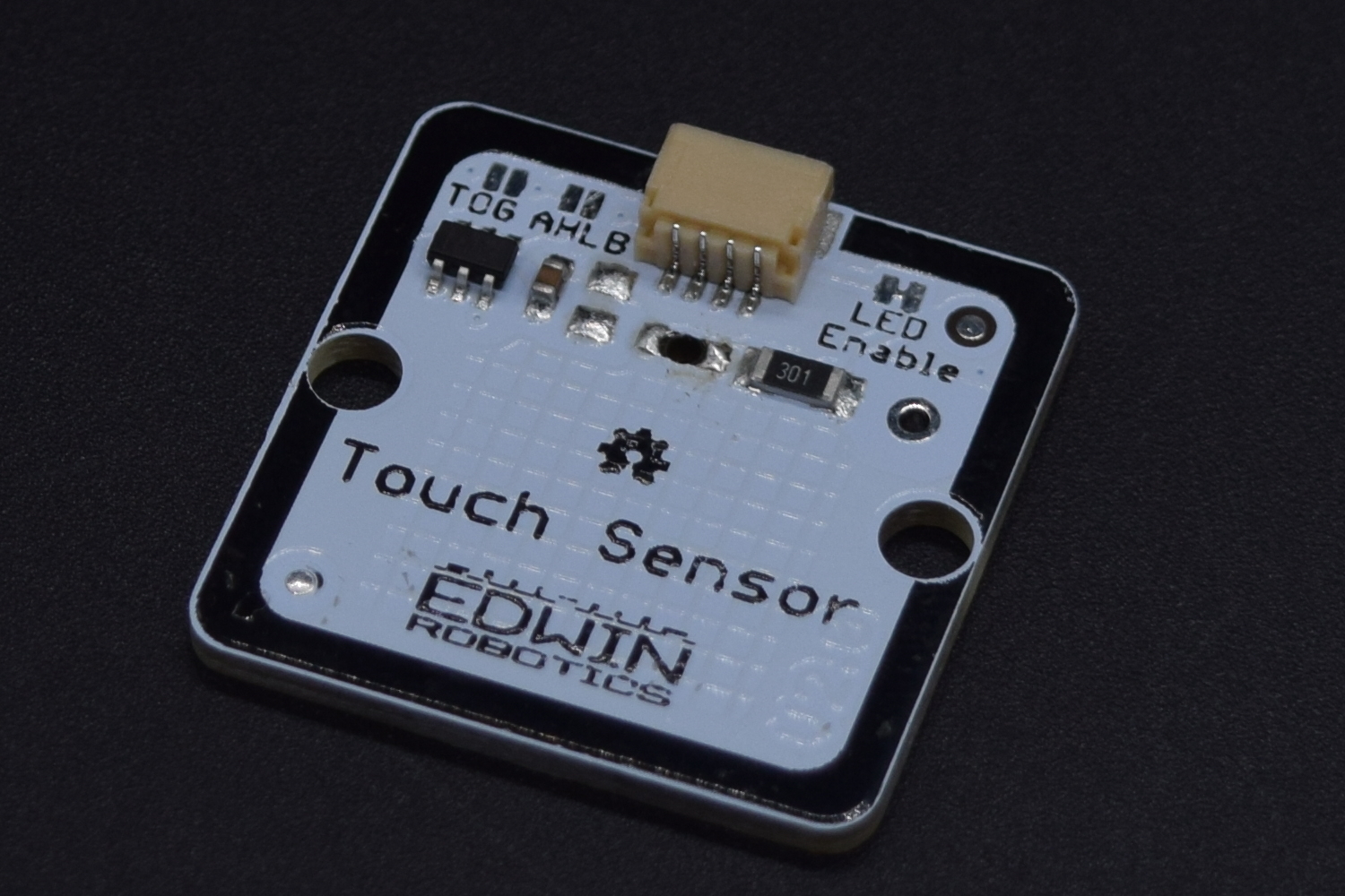
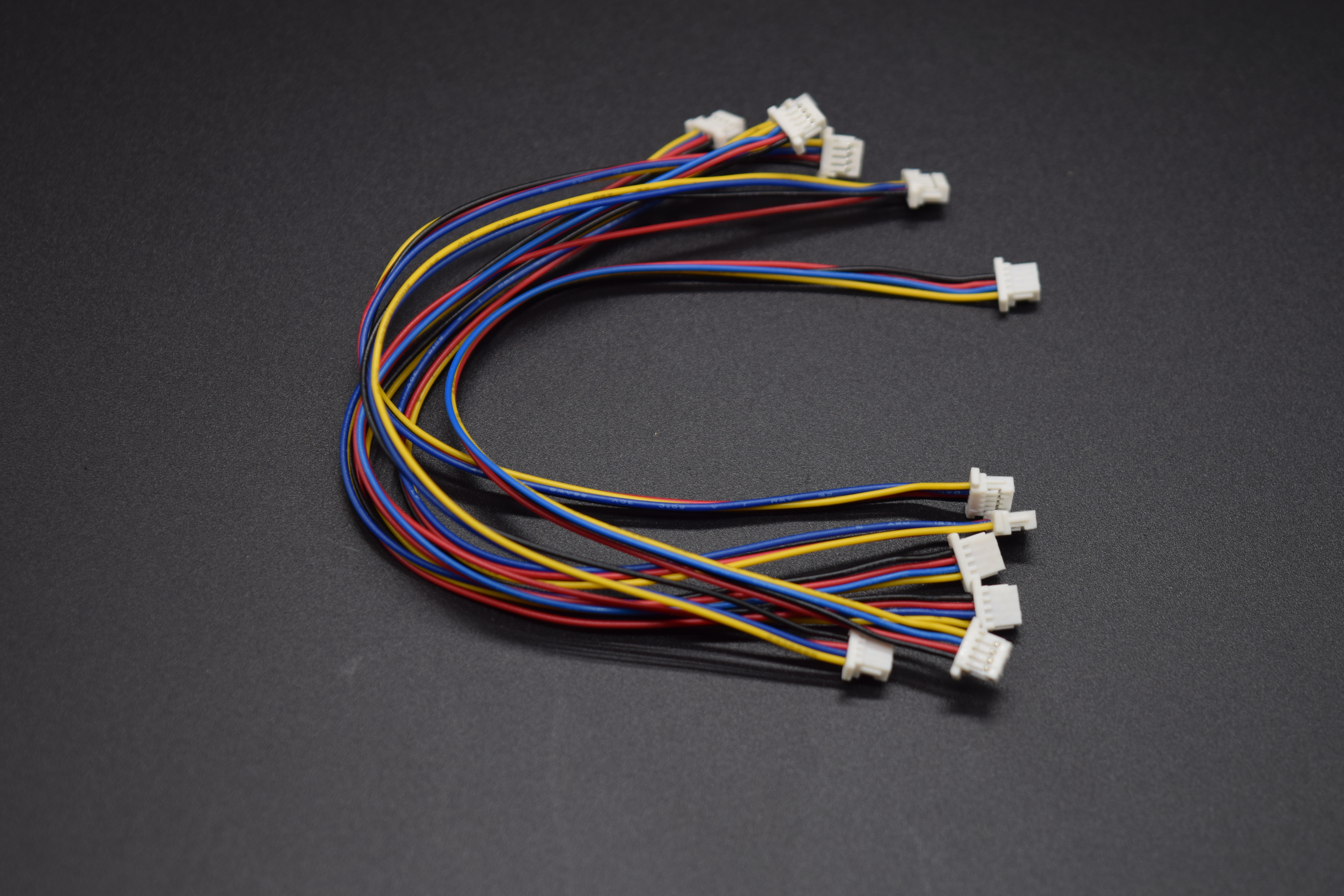
Essential for this project we will require the following items.
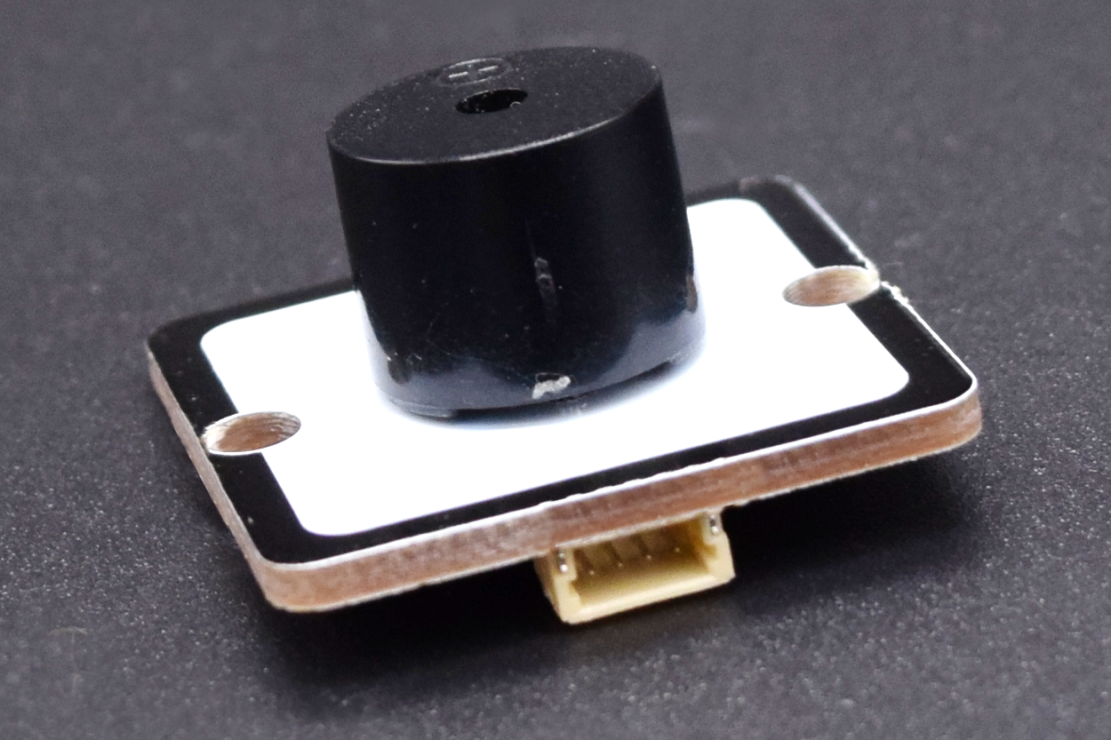
Buzzing a Buzzer using a Digital Sensor
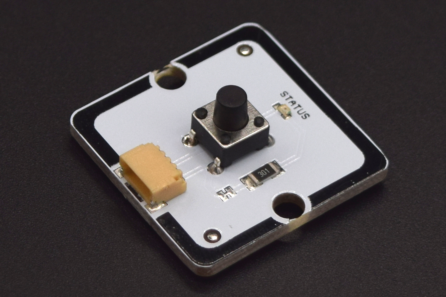
The easiest way to get introduced to your input pins is a simple project using a touch sensor and buzzer. Every time the touch sensor senses an action of touch, the buzzer should beep.
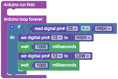
In this example – pin number 25 will be set as the input pin on which the touch sensor is connected. Pin number 12 can be set as the output pin to which the buzzer is connected.
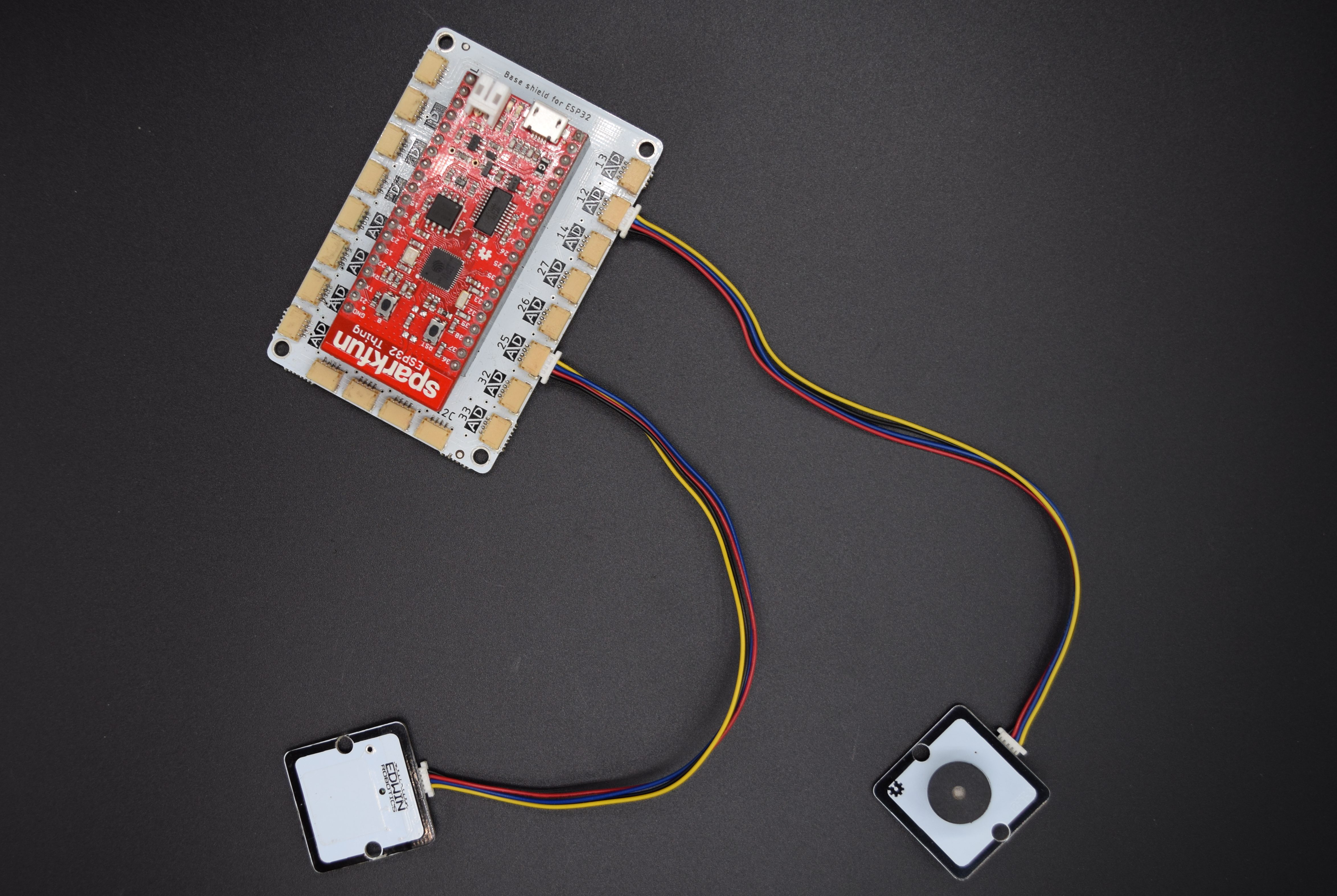
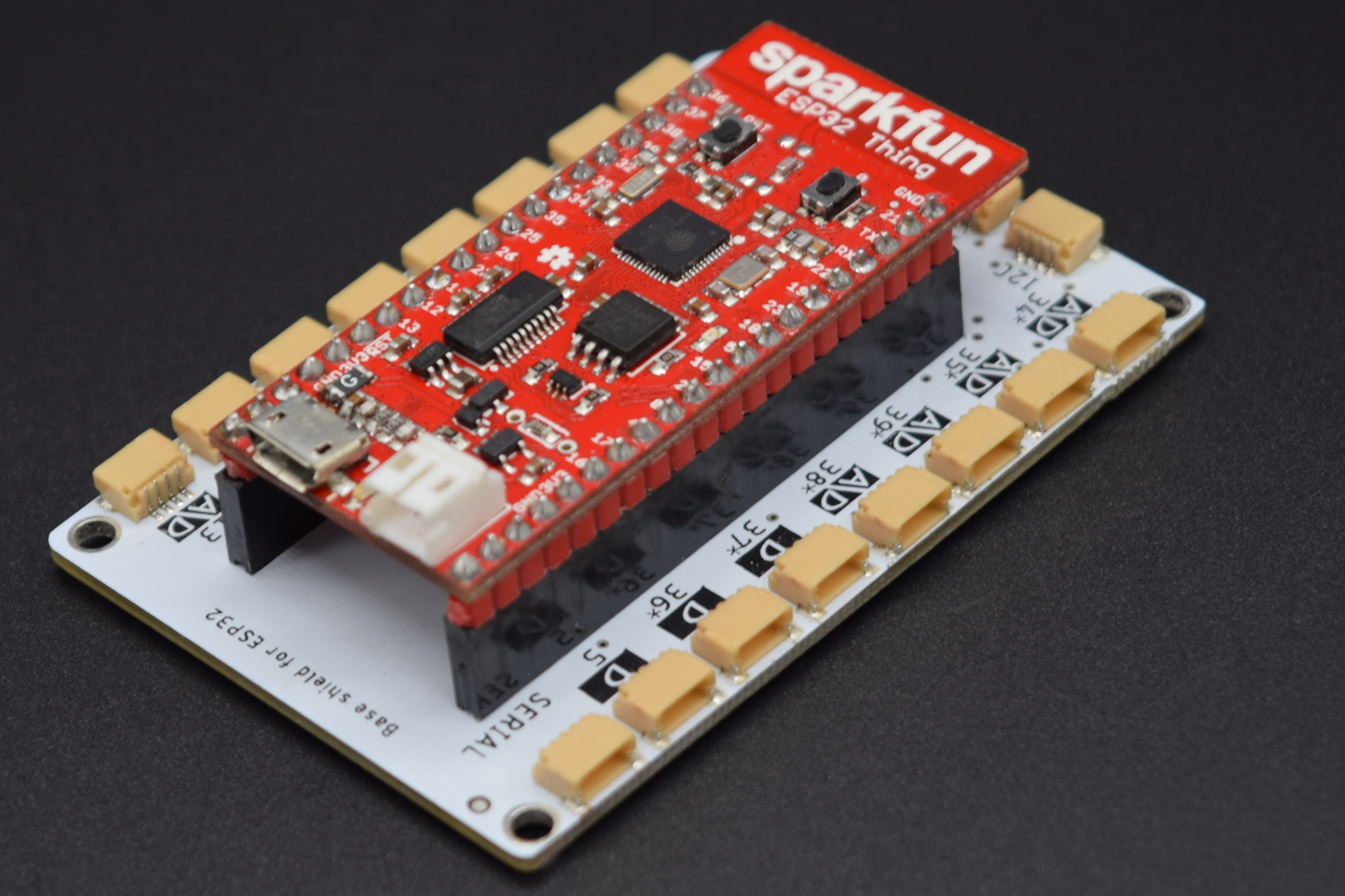
If the touch sensor is in contact with the hand the controller board (in this case SparkFun ESP32 Thing mounted on a Medusa Head) should turn on the buzzer else the buzzer should remain off. So let’s write a program when the touch sensor connected to pin number 25 turns High then the Buzzer connected to pin number 12 of Medusa Head should turn on for 1 second and turn off for 1 second. To achieve this we use an IF Block and a compare block. In the compare block, we can do various comparisons between an action and its corresponding response. In this case, we will be comparing a read digital pin block and a state block.
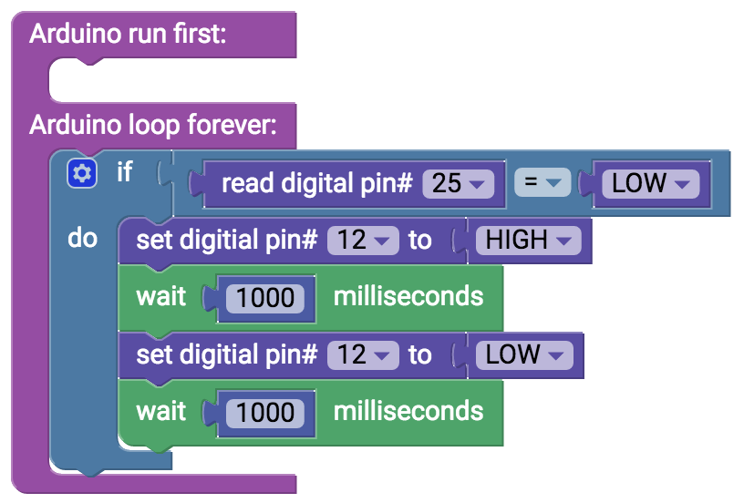
The next exercise will be replacing the touch sensor with a switch. The switch has a pull-up resistor, which makes give out a low value (zero) when pressed and when in a normal state (not pressed), it gives a high value (1). The best way to check this is by using the previous program. Unlike in the case of a touch sensor, the buzzer will turn off when the switch is pressed and turn on when release. This is not quite what is expected when we consider our understanding that every time a digital sensor is not sensing, it is at a zero else at 1. The pull-up resistor makes in a high state when not sensing and low when sensing.
Thus, replacing a touch sensor with Switch to operate the buzzer, the following sketch can be uploaded on to the board to achieve the desired output.
Block | Description |
|---|---|
 | The block for Digital Read automatically initializes the pin, by automatically calling the pin number in void setup and specifying its mode as input. |
 | The IF DO block is a comparative block found under Logic Section, as is used to execute a conditional activity. For example, if a particular event happens then do the following actions. The block has 2 sections. The section next to If is for putting the condition, and a section under Do is for the output action. |
 | This block is to specify the outputs state, high or Low. The State block can be found under the Input/Output Section |
 | The compare block can be found under logic . It has 2 sections to insert the statements to compare. In middle, there is a drop-down menu, with choice of more than, more than or equal to, less than, less than or equal to, equal to options. |
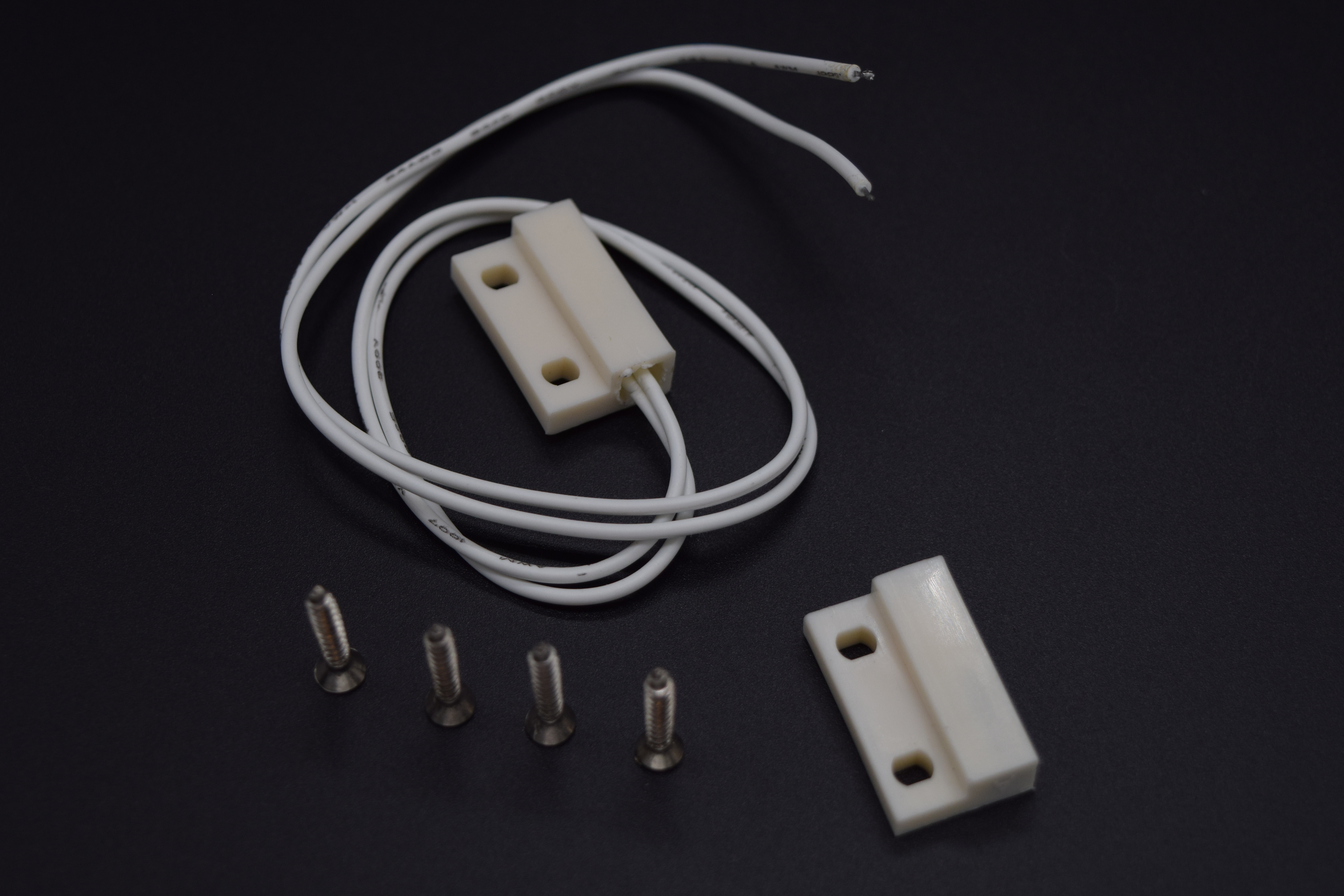
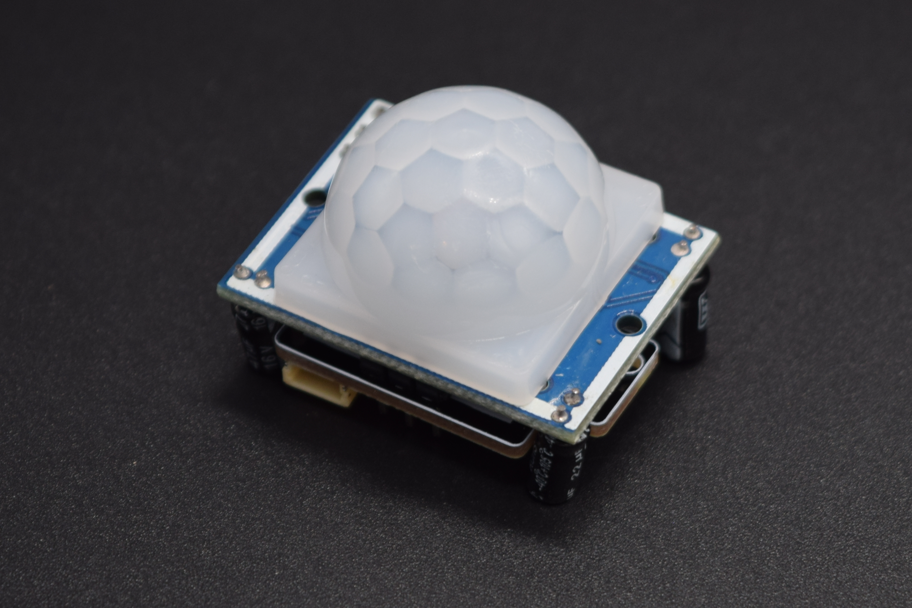
The door switch and PIR work in the same ways as the touch sensor. When not sensing their state is low and when in contact with a change they are in a high state. Now that we have covered the basic, you can try programming them.