Digital AC Mains Switch Hookup Guide

Digital AC Mains Switch
Looking to control lights and bulbs with microcontroller ? then, this digital AC switch boards is suitable for your application, this board is a great alternative for the solid state relay boards. This board comes pre-assembled with everything, all you need to do is to connect supply, load and digital interface pins.
The board posses following Electrical Characteristics:
| Parameter | Max | Unit |
|---|---|---|
| Power | 1000 (Tested) | Watt |
| Voltage | 230 (Tested) | Volt |
| Voltage | 110 (Not Tested) | Volt |
| Current | 5 (Tested) | Ampere |
| Signal | 24 | Volt |
The board is suitable to use with 3.3, 5, 12 and 24 volt systems, thus making it ideal for any voltage, the maximum ratings are mentioned in the table above and can change based on working conditions. The board is not tested on 110v lines, but its parts are compatible to work with 110V Supply. The on-board fuse are easily replaceable, in case of any damage. The mounting holes will give you the flexibility to screw it to any surface.
Connections:
All the connections must be made via screw terminals and we will recommend you to keep ready one screw driver beside you, before making connections. There are 4 screw terminals on board, please refer the image below for better idea:
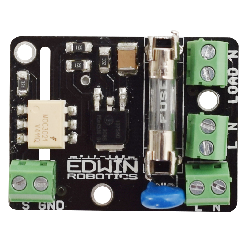
Digital AC Mains Switch Interface
Refer the below table for Silkscreen/legend description:
| Symbol | Description |
|---|---|
| Gnd | Ground |
| S | Digital Signal (Max upto 24V) |
| L | Live (To connect AC Supply Input) |
| N | Neutral |
| Load | Load (Connect to device to be controlled like Light /Bulb) |
So you need to use ‘S’ and ‘Gnd’ Pin to interface your Microcontroller board with this unit, there are two ‘L’ and ‘N’ screw terminals, you just need to connect supply to any one from the both, the second one is to extend the supply to other boards/ peripherals. Loads such as light/fan,etc. must be connected across “Load” and ‘N’ Pin to establish the connection of the load with the board. You can use jumper wires to to connect microcontroller board and screw the jumper wires to interface “S and GND “pins.
Connection Diagram:
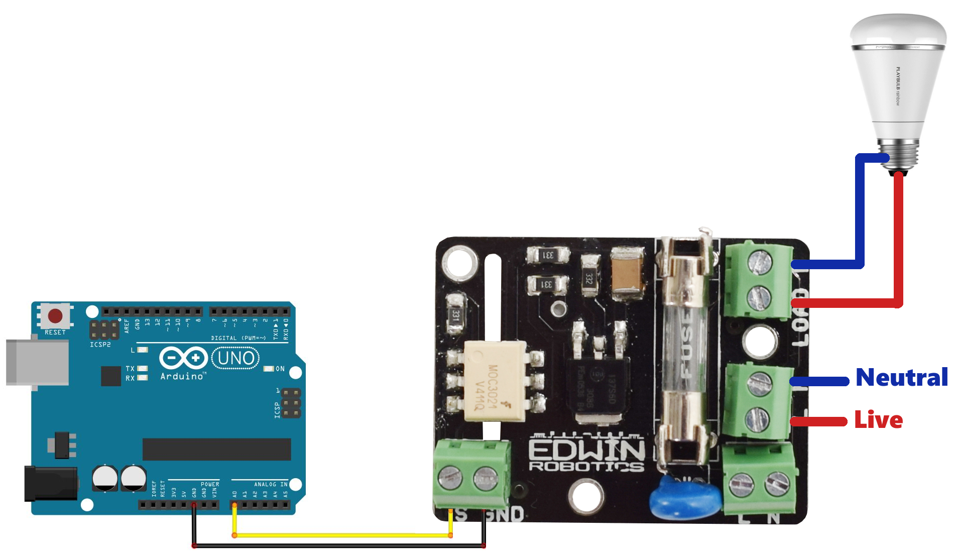
Digital AC Mains Switch connections
The microcontroller interface just needs 2 Pins, we connected Arduino ground with module ground and Arduino pin A0 as digital control for module. The load will go across Screw terminal where light bulb is connected and the power supply will go into either of the one Screw terminal.
Working with AC voltages is DANGEROUS, care must be taken to prevent any short circuits or mistakes in connection. And as always, you are doing this project at your own risk and Edwin Robotics or the Author cannot be held liable for any damages.
Sample Program:
To test the connections and board functions, we will recommend you to use the Blinking LED code from the Arduino examples, make sure to change the pin number in the code as follows:
#define LOAD A0

void setup() {
// initialize digital pin LOAD as an output.
pinMode(LOAD, OUTPUT);
}

// the loop function runs over and over again forever
void loop() {
digitalWrite(LOAD, HIGH); // turn the BULB on (HIGH is the voltage level)
delay(1000); // wait for a second
digitalWrite(LOAD, LOW); // turn the BULB off by making the voltage LOW
delay(1000); // wait for a second
}