DRV8833 DC/Stepper motor driver hookup guide
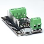
The Edwin Robotics DRV8833 breakout board is capable of controlling up to 2 DC motors or one bi/uni-polar stepper motor a max current of 1.2A. The DRV8833 comes with 2 full H-bridges which give bi-directional control of your DC motors. It is similar to the L9110S in its voltage range ( 2.7V – 10.8V), but carrying 50% more oomph. This makes it ideal for projects where the motors will be run from a 9V battery.
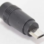
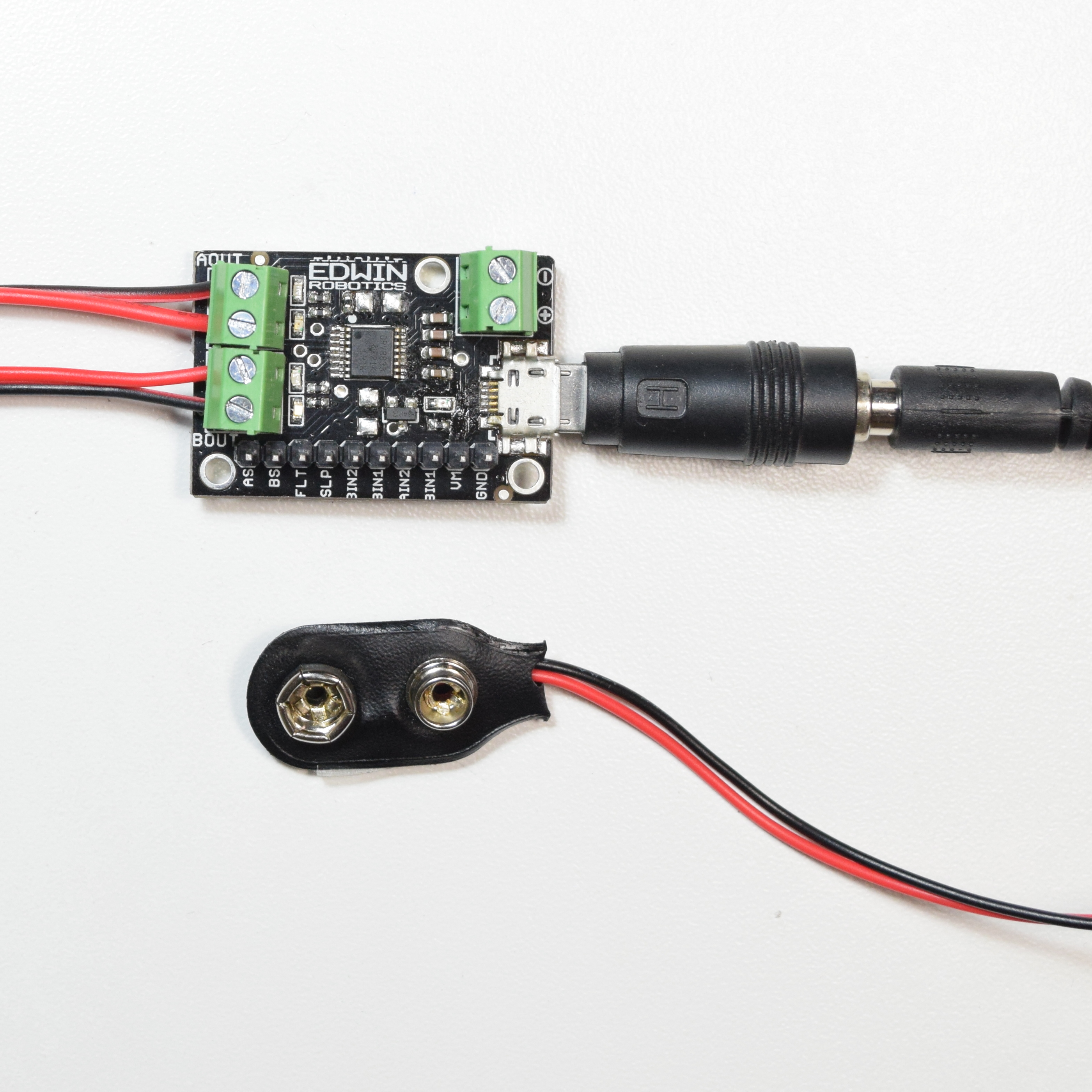
The board can be powered using the provided screw terminals or through micro-USB, checkout out micro-USB to DC Jack adapter if you would like to use a standard power adapter with the board
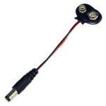
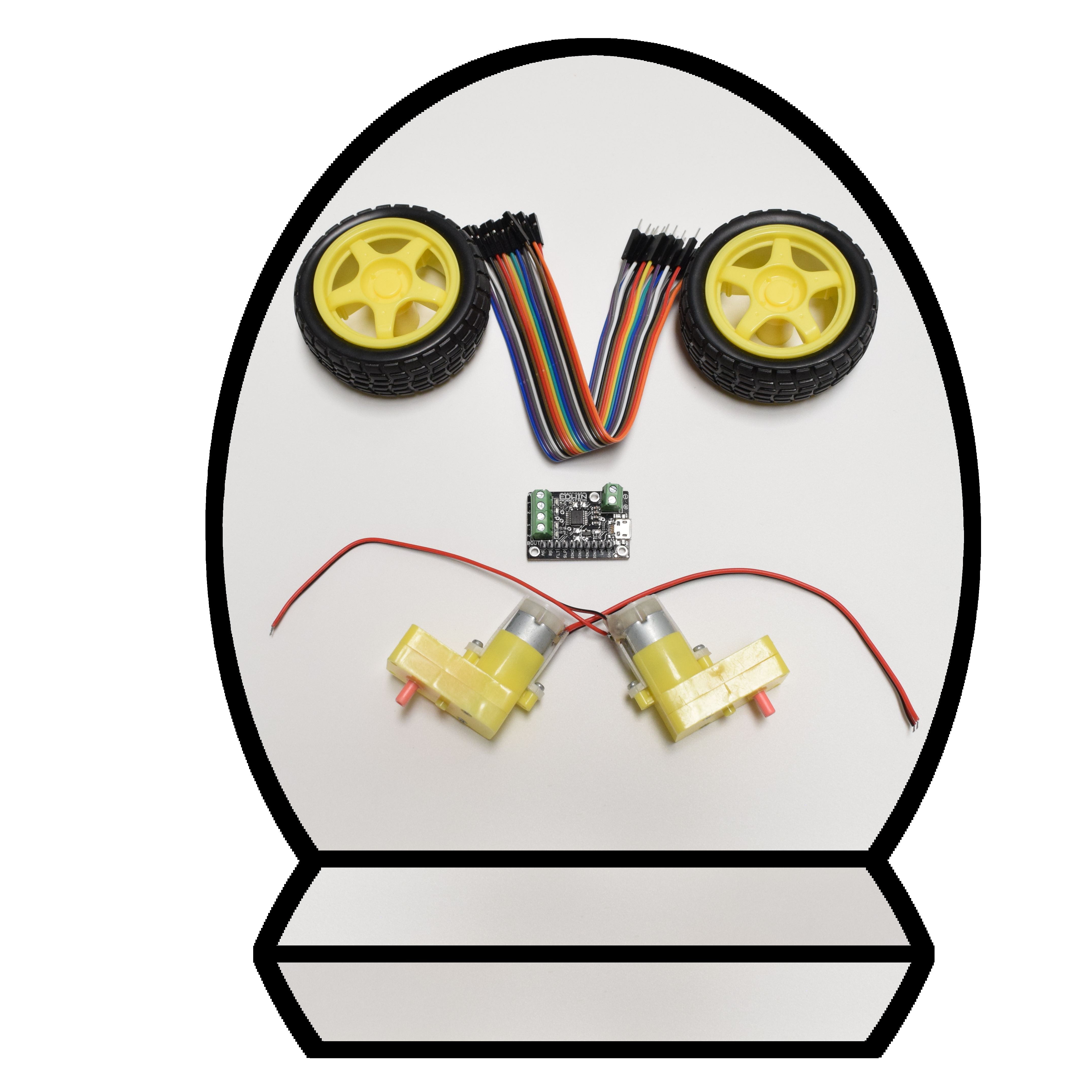
Hardware Required
Features
- Dual-H-bridge motor driver: can drive two DC motors or one uni/bi-polar stepper motor
- Operating voltage: 2.7 V to 10.8 V
- Output current: 1.2 A continuous (2 A peak) per motor
- Motor outputs can be paralleled to deliver 2.4 A continuous (4 A peak) to a single motor
- Inputs are 3V- and 5V-compatible
- Under-voltage lockout and protection against over-current and over-temperature
- Reverse-voltage protection circuit
- Current limiting can be enabled by adding sense resistors (not included)
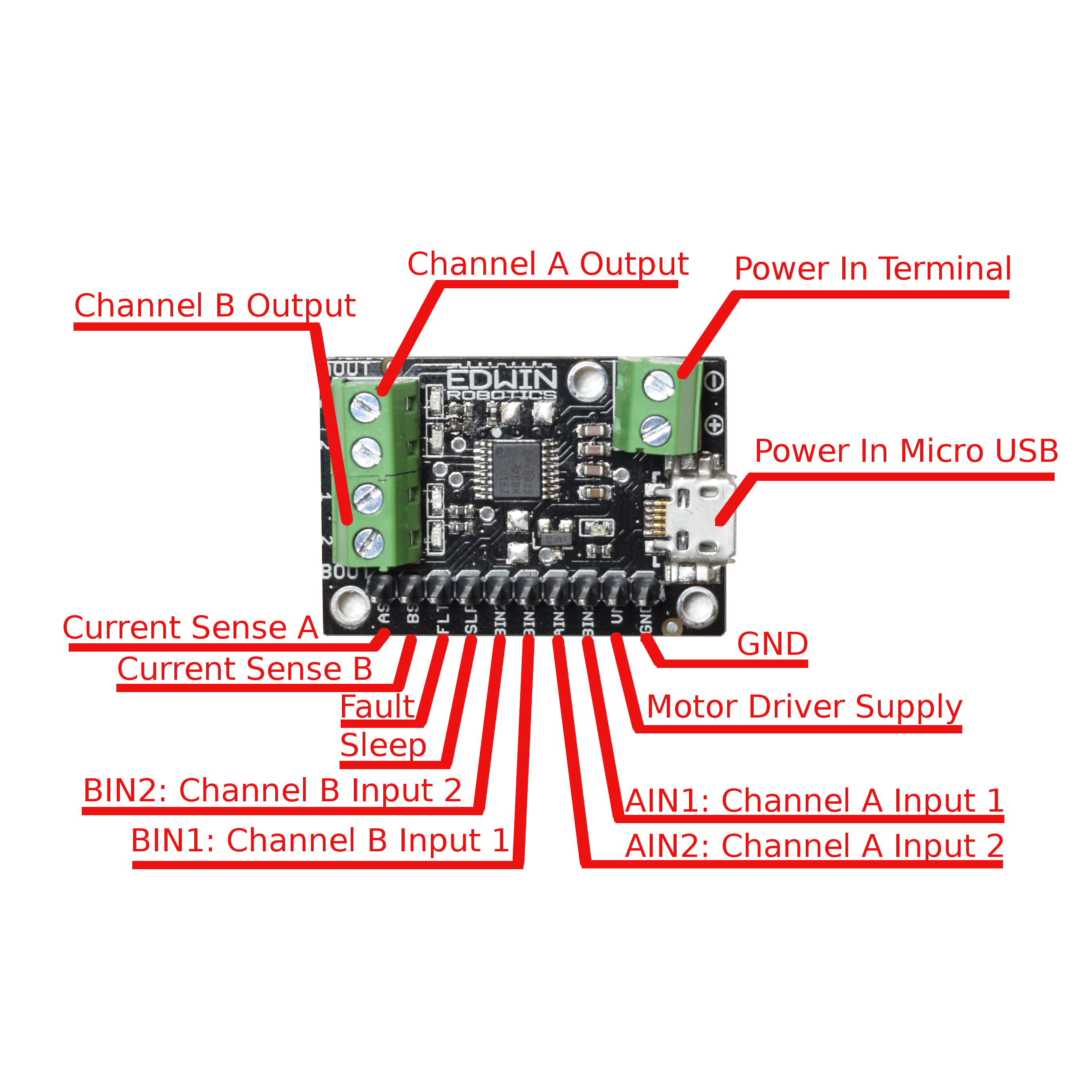
Pinouts:
Power
- Vm – This is the voltage supply for the motors. Keep this voltage between 2.7V and 10.8V. This Supply Pin is not Reverse polarity protected, so care must be taken while connecting jumper wires to it.
- Power Screw Terminal: The Power Screw terminal is labelled with + and -, connect your power supply according to label, this terminal is reverse polarity protected.
- USB Power In: You can power the board with micro USB connector provided; this is reverse polarity protected as well.
- GND – This is the shared logic and motor ground. All grounds are connected
Signals
These are all ‘2.7V or higher logic level’ inputs
- AIN1, AIN2 – Two inputs to the Motor A H-bridges. Speed control supported using PWM.
- BIN1, BIN2 – Two inputs to the Motor B H-bridges. Speed control supported using PWM.
- FLT -This is the Fault output, which will drive low if there’s a thermal shutdown or overcurrent.
- SLP – sleep pin for quickly disabling the driver. On Board 10K pullup resistor provided to keep the driver enabled.
The control inputs are pulled low internally, effectively disabling the motor driver outputs by default. See the truth tables in the DRV8833 datasheet for more information on how the inputs affect the driver outputs.
The FAULT pin is an open-drain output that is driven low by the chip whenever an over-current, over-temperature-or under-voltage condition occurs. Otherwise, it remains in a floating state, so you will need to connect an external pull-up resistor (or use a micro-controller input with its built-in pull-up enabled) if you want to monitor fault conditions on the driver.
Note: There is a misprint on Silkscreen, BIN1 is printed in place of AIN1, refer the above image for correct pinouts description.
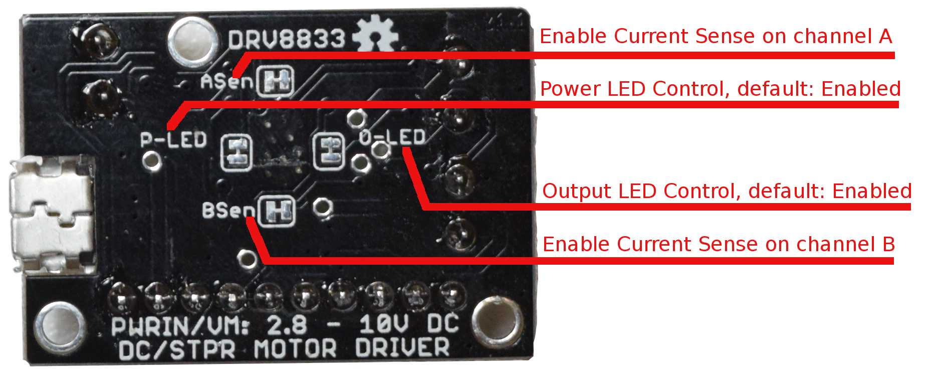
Note: we had Provided on board power LED, which will stay on whenever board is powered. You can disable the power LED with the jumper provided on the back, refer the image below for power LED (P-LED) Jumper
Current Limiting Pins
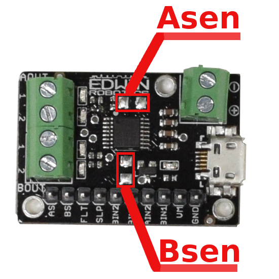
As/ Bs: The DRV8833 can perform current limiting for each motor H-bridge by connecting a resistor between As/Bs and ground to set the Motor A/ Motor B Limit.
By default , the current limiting feature is disabled and can be enabled by modifying the jumper, refer the image below:
The Current limiting can be enabled by cutting out the solder joint between the jumper Pads for Asen and Bsen. Once the jumper pads are modified you can either solder SMD resistor (1206 Size) on board or you can use the AS/BS headers pin to make connection with through hole resistors. You can also totally disable current limiting whenever needed by soldering the two jumpers on the back.
The current limiting rule is: LimitCurrent (amps) = 0.2 V / RSENSE
Connection’s
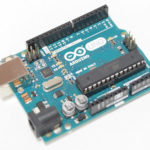
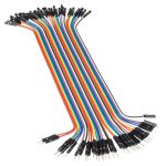
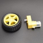
You can use any stepper motor or dc motor rated upto 10.8v with this board. We have used the following kit to get it tested:
Power Supply Connections
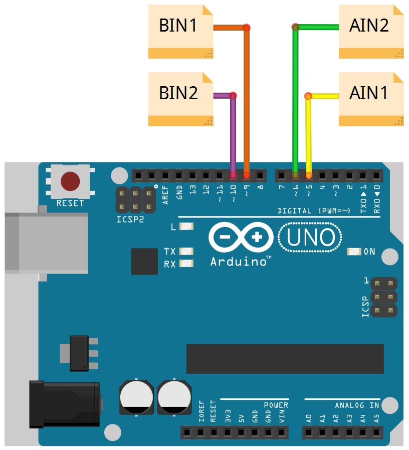
| DRV8833 Motor Driver Breakout Pins | Arduino Pins |
|---|---|
| AIN1 | 2 |
| AIN2 | 3 |
| BIN1 | 4 |
| BIN2 | 5 |
Arduino DRV8833 Connections
Test Codes
#define Ain1 5
#define Ain2 6
#define Bin1 9
#define Bin2 10

int speed = 0;

void setup() {
pinMode(Ain1, OUTPUT);  //Ain1
pinMode(Ain2, OUTPUT);  //Ain2
pinMode(Bin1, OUTPUT);  //Bin1
pinMode(Bin2, OUTPUT);  //Bin2

}

void loop() {

    digitalWrite(Ain1,HIGH);
    digitalWrite(Ain2,LOW);
    digitalWrite(Bin1,HIGH);
    digitalWrite(Bin2,LOW);
    delay(700);
    digitalWrite(Ain1,LOW);
    digitalWrite(Ain2,LOW);
    digitalWrite(Bin1,LOW);
    digitalWrite(Bin2,LOW);

    digitalWrite(Ain1,LOW);
    digitalWrite(Ain2,HIGH);
    digitalWrite(Bin1,LOW);
    digitalWrite(Bin2,HIGH);
    delay(700);
    digitalWrite(Ain1,LOW);
    digitalWrite(Ain2,LOW);
    digitalWrite(Bin1,LOW);
    digitalWrite(Bin2,LOW);

}
Download DRV8833 Datasheet
References:

