
Want to check if you left your lights ON remotely, need to detect the zero crossing point for your dimming circuit or do you just need to interface a 230V signal to your Arduino? The AC Mains Detector board simplifies interfacing high voltage signals by giving a digital output when an AC voltage is detected. By disabling the on board capacitor, zero crossing detection is possible as well.

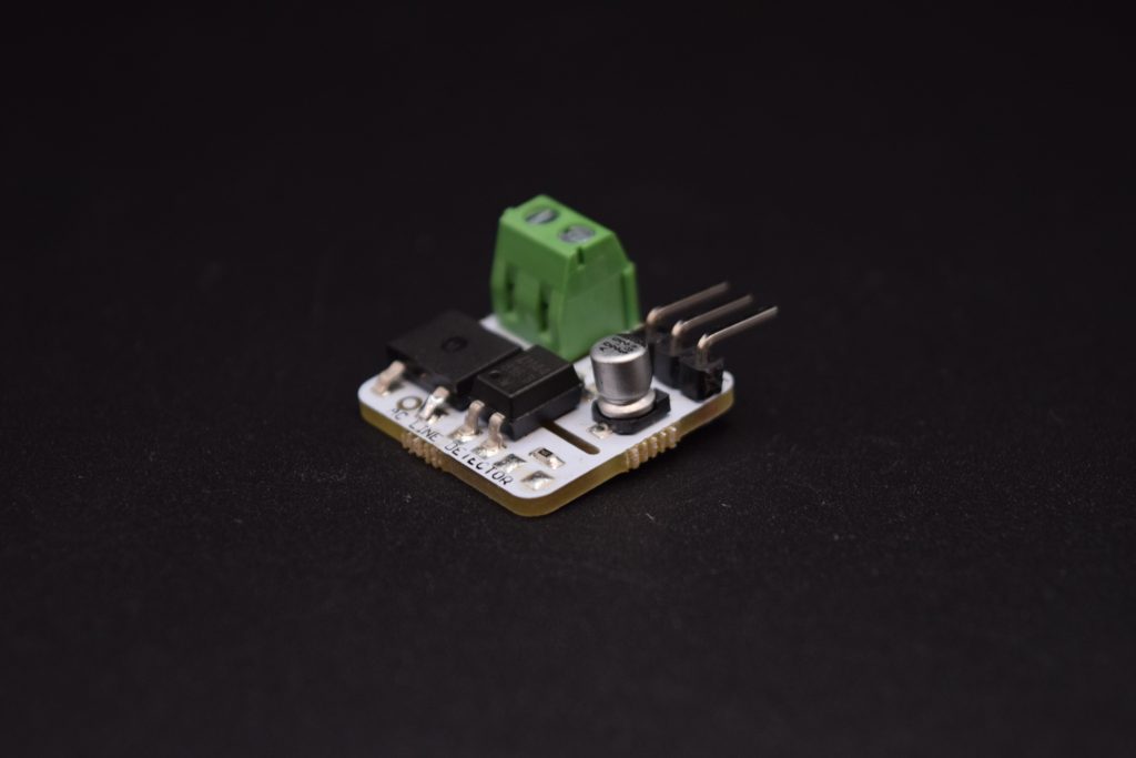
AC Line detection Module
You can buy this item from the following links:
Within GCC: Edwin Robotics
International Order: Tindie


Let us have a look at the guide contents, refer to the list below:
-
Components
-
Board Pinouts
-
Circuit Schematics
-
Interfacing with Arduino
-
Zero Crossing detection using Arduino
Components
 AC Line detection Module | 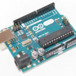 Arduino UNO | 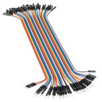 Male-Female Jumper wires |

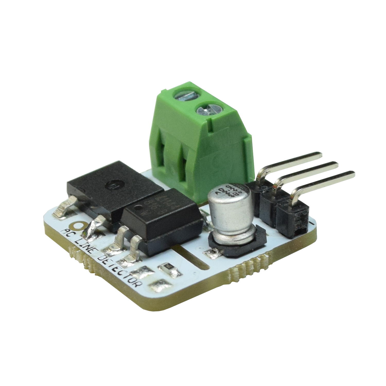
Board Pinouts
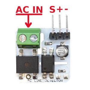 Top Side | 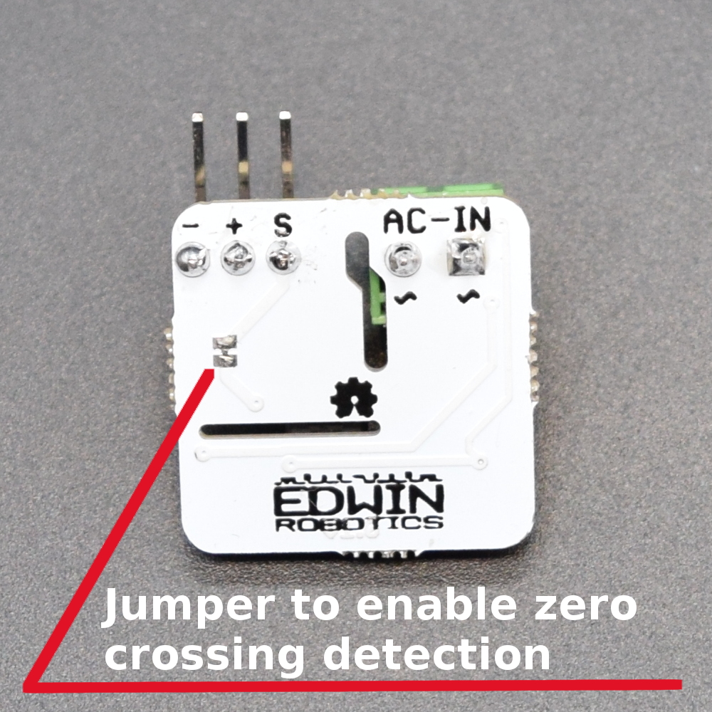 Bottom Side |

- AC-IN – Connect the AC line that needs to be detected here.
- – (negative sign) – Connect to ground of microcontroller
- + (positive sign) – Connect to VCC of microcontroller in case external pull-up is required
- S – Connect to a digital/interrupt pin of microcontroller
Note: Working with AC voltages is DANGEROUS, care must be taken to prevent any short circuits or mistakes in connection. And as always, you are doing this project at your own risk and Edwin Robotics or the Author cannot be held liable for any damages.
Circuit Schematics
The circuit consists of two main parts, first is the Bridge Rectifier (DB107) which converts the AC signal to DC and the second is the Optocoupler (LTV816), which provides isolation between High voltage(HV) side and Low Voltage (LV) Side.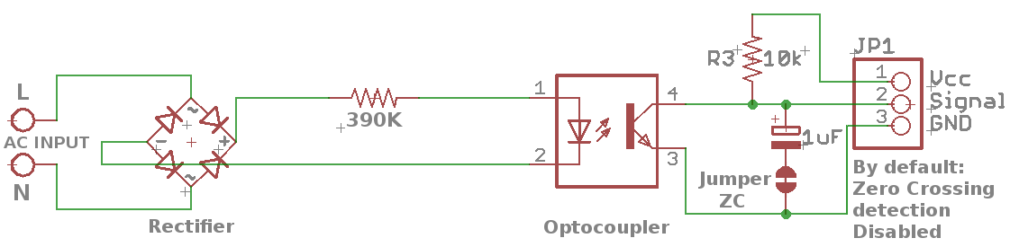
A pull-up resistor is provided for use with microcontrollers (e.g. ESP8266) that do not have an internal pullup resistor.
Interfacing with Arduino
The hardware connections are pretty straightforward. On the low voltage side the + (positive symbol) goes to VCC of microcontroller, – (negative symbol) goes to GND and S goes any digital/interrupt pin. On the high voltage side, the AC lines are connected.
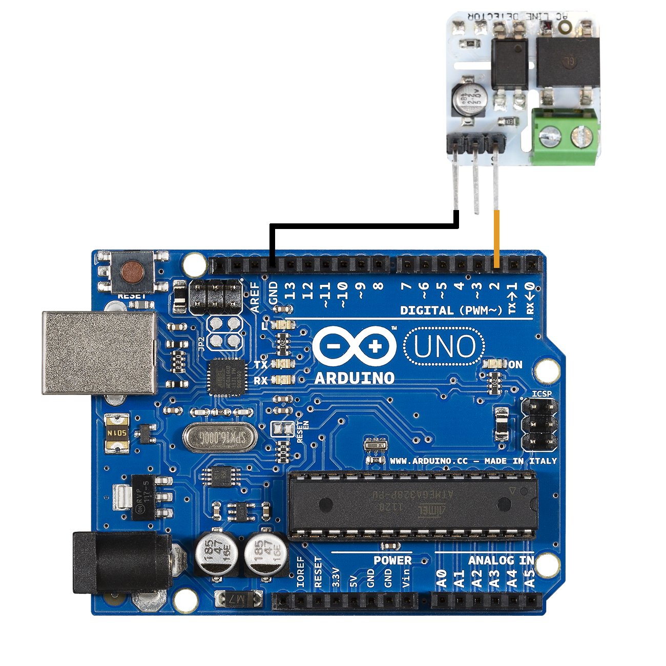
Arduino Connections
In this example, Pin 2 on the arduino is used in this example as it can be used as an interrupt pin as well.
Sample Code:
#define Signal_Pin 2  // Modify this pin as per your connection

void setup() {
  pinMode(Signal_Pin , INPUT_PULLUP);
  Serial.begin(9600);
}

void loop() {
  if ( digitalRead(Signal_Pin) == 0 )
    Serial.println (" AC Mains 230v Detected ");
}
Note: Do not touch the PCB once powered, you can get electrocuted. Keep it away from reach of humans/Animals. Make sure that there are no shorted wires, when connecting the 230v AC mains supply.
Zero Crossing Detection using Arduino
By default zero crossing detection is disabled by the use of a 2.2uF capacitor, in order to use the board for zero crossing detection the capacitor needs to be bypassed by cutting the trace shown below. It can be resoldered at any time later to disable zero crossing:
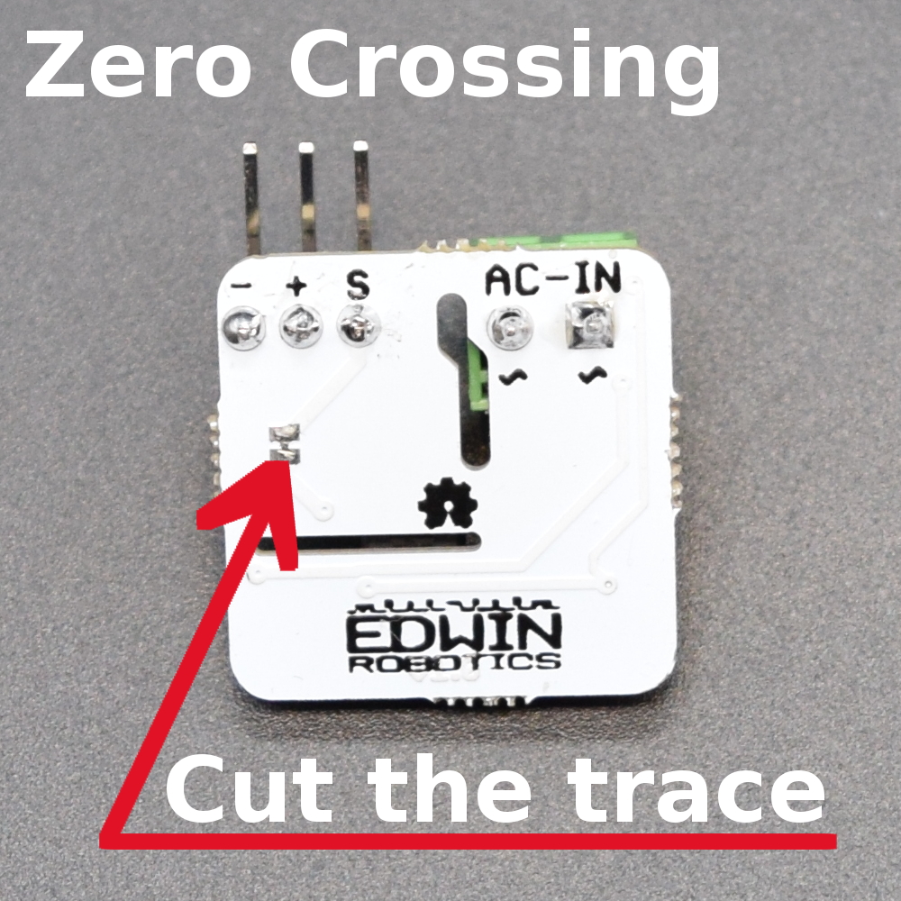
Modify the jumper
The Arduino connection will be same as before, upload the following code and view the output on Serial Monitor at 9600 baud rate:
#define Signal_Pin 2 //Use Arduino Pin 2 or pin 3, both supports hardware interrupt
int counter=0;

void setup()
{
  pinMode(Signal_Pin , INPUT_PULLUP);
  Serial.begin(9600);
  attachInterrupt(0, zero_crosss_int, RISING);  // Choose the zero cross interrupt # from the table above
}

void zero_crosss_int()  // function to be fired at the zero crossing to dim the light
{
  counter++;
}

void loop()
{
  Serial.println(counter);
}
You can see that the counter value increases with every cycle of AC line and the moment you turn off the AC line, the counter Stops as well.