Vehicle ADS
Vehicle Accident Detection System
Before we go into details of this project, I would like to give you some idea about what this project is all about. This is a DIY project suited for anyone who are interested to build a prototype using any old RC cars, but do not limit yourself just to RC cars or toys itself, You are all free to modify it as per your ideas and imagination. Beginners can give it a try for sure but there is some level of skill needed to finish this project. You are going to learn some electronics hardware interfacing in addition to programming during this project.
The objective of this project is to build a vehicle which is capable enough to inform the Emergency Service and the pre-programmed contact number about the accident. Accident detection systems help reduce fatalities stemming from car accidents by decreasing the response time of emergency responders.
Smartphones and their onboard sensors (such as GPS receivers and accelerometers) are promising platforms for constructing such systems. Thus we will try to replicate the functions of smartphones and some sensors to build this project.
I used the following components to build this project:
Components List
- Arduino UNO
- GSM Shield
- Sparkfun GPS Shield
- Sparkfun 6DOF IMU
- Sparkfun RedBot Sensor- Mechanical Bumper
- LCD 16X2
- Antenna
- Potentiometer
- DC Jack Battery Connector
- 9v Battery Snapper
Follow the Steps below to finish it without having any issues.
Collision Detection Using Mechanical Bump Sensor
Detect roll using 6DOF IMU
Display Information using 16 x 2 LCD
Tracking location using GPS
Sending Messages using GSM Module
Complete Setup
Collision Detection Using Mechanical Bump sensor
I used the Sparkfun RedBot Sensor- Mechanical Bumper to start the collision detection.
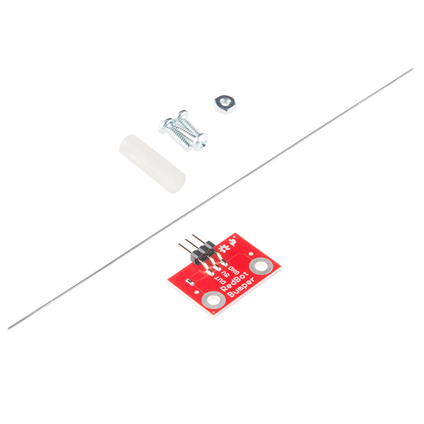
Connections to this module is very simple. You need to use jumper wires to connect GND and OUT pins (not the 5v pin). Now take out your ARDUINO UNO and connect as mentioned:
Sensor OUT Arduino A3
Sensor GND Arduino GND
Run the following code in your Arduino
void setup() {
Serial.begin(57600);
pinMode(A3, INPUT_PULLUP);
}void loop() {
if(digitalRead(A3)==0){
Serial.println(“detected”);
delay(200);
}
}
Once code is uploaded, you need to open the Serial monitor at 57600 baud rate, you are able to see that whenever you press the bumper from hand, it will show the message detected.
Detect roll using 6DOF IMU
In case of accident the car will either roll or it will create a sudden jerk movement, Our job is to detect this roll and jerk from the car, for this we will use the Sparkfun 6DOF IMU
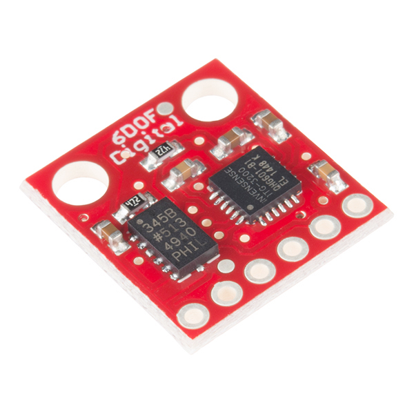
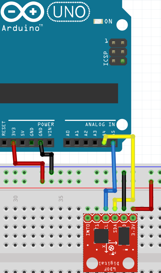
It’s a Small tiny board with Accelerometer and Gyroscope Together on the same board with six degree of freedom. The board uses I2C communication and requires 3.3v power supply.
Connect the board as shown in the figure below:
You need to run the following code in the Arduino, but before that make sure you added all the necessary library for the same.
Refer this link to download the latest version of library:
http://code.bildr.org/project/6dof/Arduino
or
Visit the Following link to download the Zip File:
http://code.bildr.org/download/985.zip
Once you download the library, make sure you unzip it and copy it to Arduino libraries.
You need to restart the Arduino after this step.
Use the following code to detect the yaw, pitch and roll from the Sensor.
#include <FreeSixIMU.h>
#include <FIMU_ADXL345.h>
#include <FIMU_ITG3200.h>
#include <Wire.h>
#define limit1 165
#define limit2 165
#define limit3 165float y_p_r[3];
boolean yaw=false, pitch=false, roll=false;FreeSixIMU sixDOF = FreeSixIMU();
void setup() {
Wire.begin();
delay(5);
sixDOF.init(); //begin the IMU
delay(20);
}void loop() {
sixDOF.getYawPitchRoll(y_p_r);if( (abs(y_p_r[0]) > limit1))
yaw = true;
else
yaw = false;if( (abs(y_p_r[1]) > limit2))
pitch = true;
else
pitch = false;if( (abs(y_p_r[2]) > limit3))
roll = true;
else
roll = false;if(yaw==true){
Serial.println(yaw);
yaw=false;
}if(pitch==true){
Serial.println(pitch);
pitch=false;
}if(roll==true){
Serial.println(roll);
roll=false;
}}
Modify the parameter limit1,limit2 and limit3 in the code as per your requirement and make sure you are able to get the output with different orientation and tilt of the board.
Display Information using 16 x 2 LCD
Most of the Vehicle ADS have onboard display to show the various Information, In this project we will use the 16 x 2 LCD to display our information, you can use any display as per your convenience but I opt this one because it’s cheaper and you are able to get it easily from the local shop.
Refer the Diagram below to connect the LCD

To test the LCD, you just need to follow the Arduino Examples Section, there you will find LiquidCrystal, just run any of the examples sketch and check whether you are able to get any output or not. Make Sure you modify the LCD pin connections in the example Code, otherwise you will not see the desired output.
Below I have added the LCD initialization for the connections shown in the image, if you had followed the same pin structure then you just need to copy paste it in the example sketch.
LiquidCrystal lcd(6, 12, 8, 9, 10, 11);
Tracking location using GPS
Location tracking is something we have seen in several devices like mobile phones, metro trains, buses and your own vehicles and most of them uses GPS to find out the position. We will use this GPS Receiver – LS20031 to find out the current location of device.
Sparkfun has provided great tutorial on their website to get started with this device, follow the instructions here:
https://www.sparkfun.com/tutorials/176
Perform the Quick test to see the output from the GPS.
Once you done with Setting up the GPS Receiver, it is really easy to get the desired reading, all thanks to TinyGPS library, which will give you the locations in formatted manner, all you need to do is to access the position from the library function itself.
Visit this link to download the latest version of the TinyGPS library:
https://github.com/mikalhart/TinyGPS/releases/tag/v13
Or
you can download the zip file directly from this link:
https://github.com/mikalhart/TinyGPS/archive/v13.zip
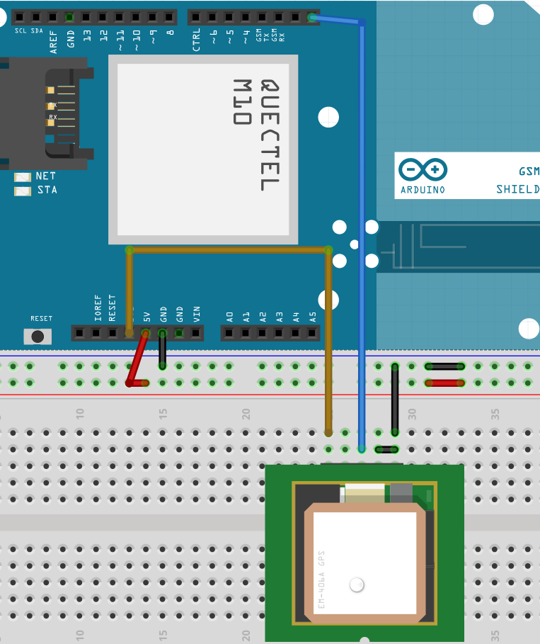
Once you are done setting up the library for the Arduino, restart the Arduino software, refer the diagram below to display the GPS Location in LCD.
Note** Care must be taken while connection GPS, since its runs on 3.3v and you are interfacing it with 5v System, thus any voltage level greater than 3.3v will damage the GPS module, this is why we did not used the Rx pin on the GPS, if you need to use RX pin on 5v system, you must add logic level shifter like: https://www.sparkfun.com/products/12009 between Arduino and GPS.
Use the following code to test the GPS and LCD:
#include <TinyGPS.h>
#include <LiquidCrystal.h>TinyGPS gps;
LiquidCrystal lcd(6, 12, 8, 9, 10, 11);static void smartdelay(unsigned long ms);
void setup()
{
Serial.begin(57600);
lcd.begin(16, 2);
}void loop()
{
float flat, flon;
unsigned long age;gps.f_get_position(&flat, &flon, &age);
lcd.setCursor(0, 0);
lcd.print(“LAT:”);
delay(5);
lcd.print(flat,3);
delay(5);lcd.setCursor(0, 1);
lcd.print(“LON:”);
delay(5);
lcd.print(flon,3);smartdelay(1000);
}static void smartdelay(unsigned long ms)
{
unsigned long start = millis();
do
{
while (Serial.available())
gps.encode(Serial.read());
} while (millis() – start < ms);
}
Advanced users can modify the code and connections to use any of the Arduino GPIO pin to be used as RX Pin using Software Serial Library, this is useful because while GPS Connected to RX Pin of Arduino you are not able to upload the code to the Arduino, it will give error while uploading, in case you face this issue, make sure to remove the jumper from Arduino RX pin.
Sending Messages using GSM Module
Now the most important function of this system is to deliver the alert messages to others in case of an accident, for this we will use the Arduino GSM Shield, GSM Shield has built in SIM slot, all you need to do is to insert a working SIM having some balance to send the messages.
For more advanced details refer this Link: https://www.arduino.cc/en/Guide/ArduinoGSMShield
We will try to integrate GPS and GSM together in this section, please refer the diagram below for required connections.
Now all you need to do is use the following code to see the working of the device.
#include <GSM.h>
#include <TinyGPS.h>#define PINNUMBER “” // If your SIM has PIN, pass it as a parameter of begin() in quotes
TinyGPS gps;
boolean MessageSent = false;
// initialize the library instance
GSM gsmAccess;
GSM_SMS sms;float flat, flon;
String txtMsg =”Owner:Abhishek\nLicense: KLNA2\nAccident Alert!!!!!!!\n”;static void smartdelay(unsigned long ms);
void setup(){
boolean notConnected = true;
Serial.begin(57600);while (notConnected)
{
if (gsmAccess.begin(PINNUMBER) == GSM_READY)
notConnected = false;
delay(1000);
}
}void loop(){
char remoteNum[]=”0562xxxxx0″; // telephone number to send smsunsigned long age;
gps.f_get_position(&flat, &flon, &age);Serial.println(txtMsg+”LON: ” + String(flon)+ ” LAT: ” + String(flat));
if(!MessageSent){
sms.beginSMS(remoteNum);
sms.print(txtMsg+”LON: ” + String(flon)+ ” LAT: ” + String(flat));
sms.endSMS();
MessageSent = true;
}
}
static void smartdelay(unsigned long ms)
{
unsigned long start = millis();
do
{
while (Serial.available())
gps.encode(Serial.read());
} while (millis() – start < ms);
}
The above code will continuously print the GPS location in the Serial Terminal also it will send the formatted message to designated number once.
Complete Setup
This step is the most important part, here we will put things together, following all the steps one by one make sure that all the things in the project are working upto the mark, I am expecting you are able to get the desired output till step4.
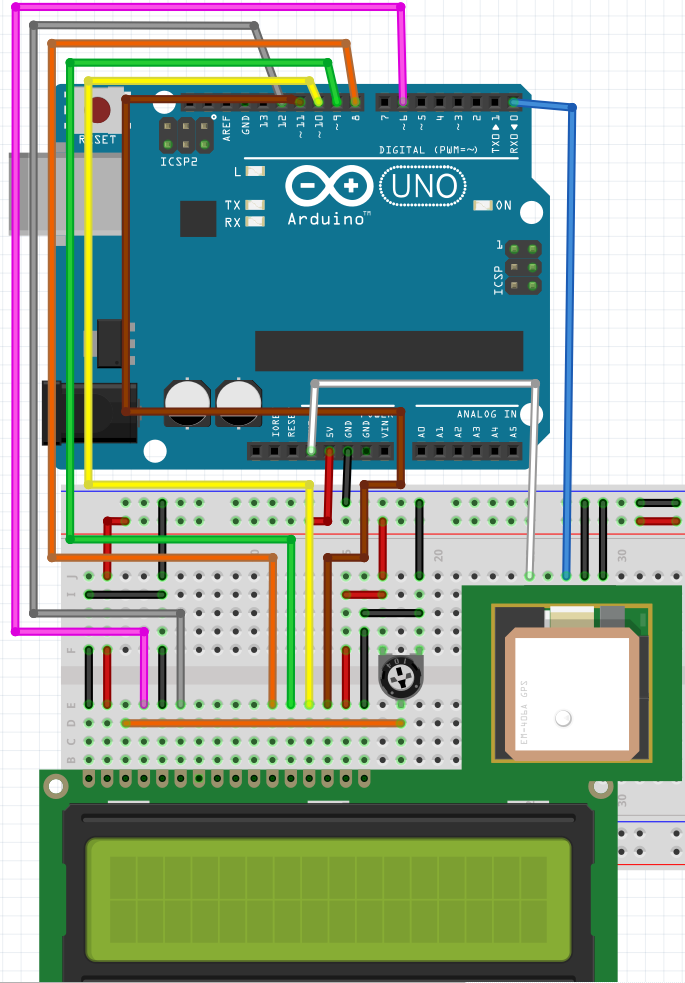
We will first start with hardware Integration part, I had made things easier for you. Just refer the diagram I attached below as reference.
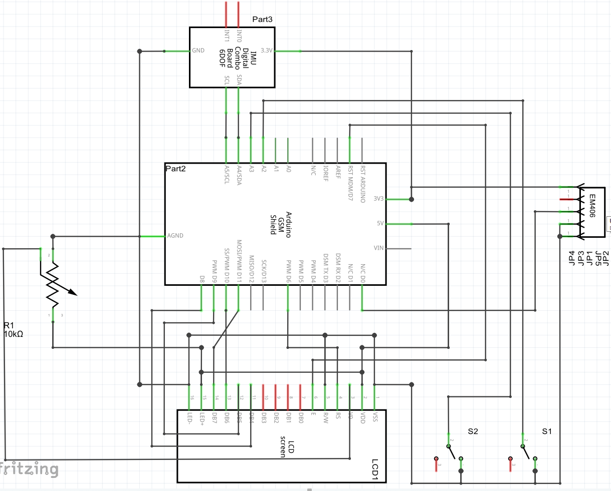
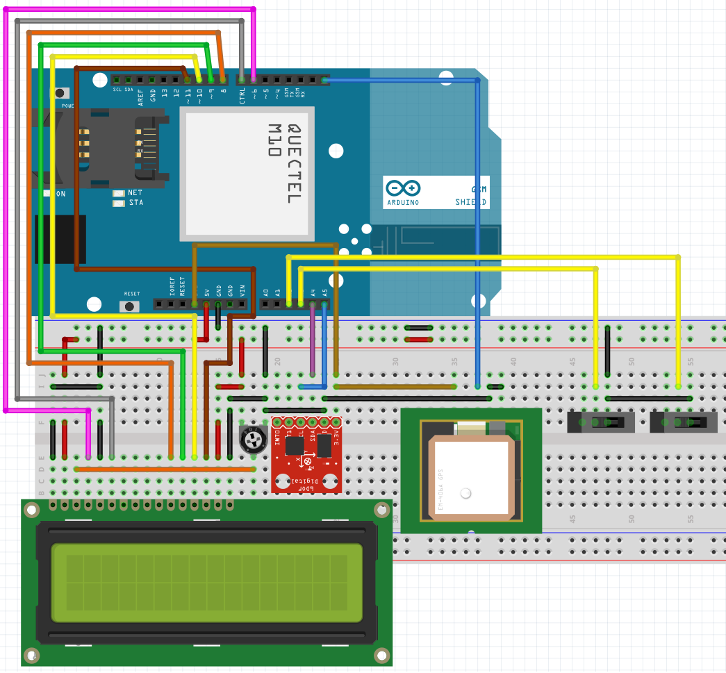
In the above image I had used SPST Switch in place of mechanical bump sensor since I was unable to found the part in the fritzing software, so no need to be confused with that part. Most of the sections we already tested individually. Just make sure you follow the connections exact same way, crosscheck twice or thrice before we move to software part.
I had used the Fritzing software to make my work easier, it’s really helpful tool to make connections faster in breadboard and get the schematics ready.
I had used the following program to get the final prototype ready and in working condition.
#include <FreeSixIMU.h>
#include <FIMU_ADXL345.h>
#include <FIMU_ITG3200.h>
#include <LiquidCrystal.h>
#include <Wire.h>
#include <TinyGPS.h>
#include <GSM.h>#define limit3 165 //roll // Increasing the value can decrease the sense range of the IMU, Decreasing the value can sense the minute vibrations, tilt or accelaration, update this incase you need it
#define debounce 100
#define bumper1 A2
#define bumper2 A3LiquidCrystal lcd(6, 12, 8, 9, 10, 11);
TinyGPS gps;
GSM gsmAccess;
GSM_SMS sms;char remoteNum[]=”05xxxxxx74″; // telephone number to send sms “Update this part only”
float y_p_r[3];
boolean roll=false;
boolean hit=false;FreeSixIMU sixDOF = FreeSixIMU();
void setup() {
boolean notConnected = true;lcd.begin(16, 2);
lcd.setCursor(0,0);
lcd.print(“Please wait”);while (notConnected)
{
if (gsmAccess.begin() == GSM_READY)
notConnected = false;
delay(1000);
}lcd.begin(16, 2);
lcd.clear();Serial.begin(57600);
pinMode(bumper1, INPUT);
pinMode(bumper2, INPUT);
digitalWrite(bumper1, 1);
digitalWrite(bumper2, 1);
Wire.begin();delay(5);
sixDOF.init(); //begin the IMU
delay(1000);lcd.clear();
lcd.print(“Setup complete “);
delay(2000);
lcd.clear();}
void loop() {
float flat, flon;
unsigned long age;for(int i=0; i<5; i++){
while (Serial.available())
{gps.encode(Serial.read());}
delay(100);
}gps.f_get_position(&flat, &flon, &age);
if((digitalRead(bumper1)==0) || (digitalRead(bumper2)==0))
{
delay(debounce);
hit=true;
}sixDOF.getYawPitchRoll(y_p_r);
if( (abs(y_p_r[0]) > limit3) ||(abs(y_p_r[1]) > limit3) ||(abs(y_p_r[2]) > limit3))
roll = true;
else
roll = false;if(hit==true || roll ==true)
{
if((flon == 1000.000) && (flat==1000.000)){
flon=54.39;
flat=24.45;
}lcd.setCursor(0,0);
lcd.print(“Abhi N3AB4″);
delay(2000);
lcd.clear();String txtMsg =”Owner:Abhi \nLicense: N3BA4\nAccident Alert!!!!!!!\n”;
sms.beginSMS(remoteNum);
sms.print(txtMsg+”LON: ” + String(flon)+ ” LAT: ” + String(flat));
sms.endSMS();hit=false;
}
}
While compiling this code you might get the message that Sketch too big, it really took some time for me to get this thing sorted out. I did modified the library files to make its size within the limit, the next part you can do is to remove or modify the string in the code and it will save you more space. I will share you the library which I modified so as to get it in working condition.
Sometimes GPS might not work inside the house and it will give you location as 1000,1000
so don’t worry with this, it’s not code issue, it’s the GPS, when you take it out under open sky, you will see the coordinates are updated and the red led on the module started blinking. Hope you enjoyed this project, expecting your valuable feedback. Will join you soon with more interesting project.