Tutorial: Breadboard Power Supply
There are cases when you need to rely on battery source to run your projects, like robotics based projects or any kind of portable projects where you need to consider weight, cost, complexity and lots of parameter for power supply. Once such Preferred source of power is a 9v Battery. Its small, cheap, simple, light weight and easily available in local market but there are limitations too with this power source, like current is limited and you need to cascade multiple battery to provide more current to the circuit. Battery Discharges after limited operations but if you buy rechargeable ones. it will save you lots money and time.
Most of the system either works on 5v or 3.3v and if we powered these devices straight from 9v battery, chances are there that it will damage the devices. In these case a voltage regulator will comes handy. There are different kinds of voltage regulators available in the market and based on your application you are free to opt for any of them. Here we are going to show you how to use a voltage regulator to step down the voltage from 9v to 5v or 3.3v
The most common and preferred voltage regulator is 7805, which is capable of regulating voltage supply out to 5v. This regulator is preferred because its cheap and easily available in local market, capable for high current sourcing i.e 1.5A, which is reasonably enough for most of the applications and circuit complexity is less, just some capacitors and you are ready to go. In addition to this vast Input voltage range(max upto 35v and 40v in some variant). The 78xx voltage regulator family comes in different configuration, so all you need to do is select you desired output voltage and buy the corresponding regulator, like 3.3v, 9v, 12v, etc.
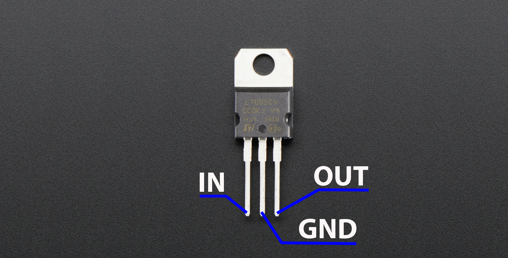
Lets see the Pin configuration of the 7805 voltage regulator:
We will use this voltage regulator to build a standard 5v power supply for breadboard, so that you don’t have to worry about supply Input. Adding this power supply to your breadboard will give you the flexibility to use any of the battery source. We will recommend you to dedicate one corner section of the breadboard for the voltage regulator, so that you don’t have to plug-unplug it for every other applications. Now let us show you how to build a simple breadboard power supply, refer the below diagram for better idea.
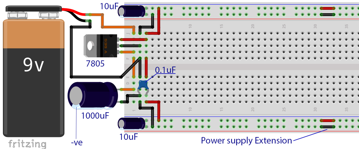
The circuit shown above is really simple, we had used four capacitors in total which you can reduce to three also. Let me describe you the purpose of these capacitors, one by one:
- 1000uF capacitor: If you look in the circuit, you can see one 1000uF polarized capacitor, the polarity matters to this capacitors, thus you need to take care of its polarity while connecting. Silver strip indicates the position of negative leg of the capacitor. The purpose of this capacitor is to store the charge before supplying anything to the voltage regulator, i.e it act as global reservoir, thus making it sure that supply to the voltage regulator from the battery source will always remains constant.
- 10uF Capacitor: These are nothing but local reservoir which will store the charge before supplying to the circuits, thus making sure that there is always a constant power supply across all the parts. We used two 10uf polarized capacitors in the circuit because we want both the parallel outer tracks of the breadboard to be supplied with constant power. You can fit in just one capacitor next to 7805 Out pin.
- 0.1uF Capacitor: we had used one ceramic capacitor in the output of 7805 voltage regulator, just to filter out any unwanted voltage spike(ripples) also called as noise, thus these tiny ceramic caps can act as filter element in the power supply you built. The polarity of these capacitors does not matters at all, you can use it either way.
Note: There are breaks in the outer tracks of breadboard, exact in the center portion, refer the diagram above, we had used wires as jumper to extend the power supply further, mentioned as power supply extension in the diagram.
The orange line shown in the image above is Input to voltage regulator, you can supply upto 35v to this wire to get a constant regulated 5v output voltage. If you supply high voltage to voltage regulator like 12v or 24v, you will see that voltage regulator getting hot, this is because of voltage regulator power dissipation in the form of heat to covert that much high voltage to 5 volt out. Don’t touch your fingers or hands to regulator in case its hots and if you feels that voltage regulator getting hot every time, then its better to use use Heat sink for voltage regulator.
This project details the design of a very low dropout adjustable power supply.